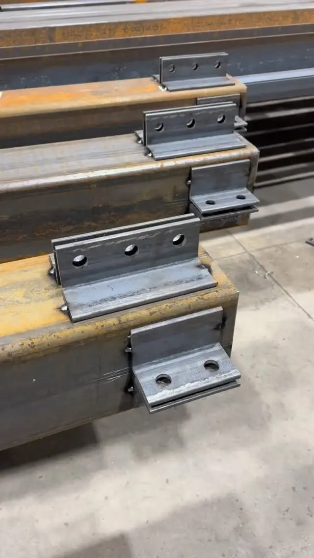
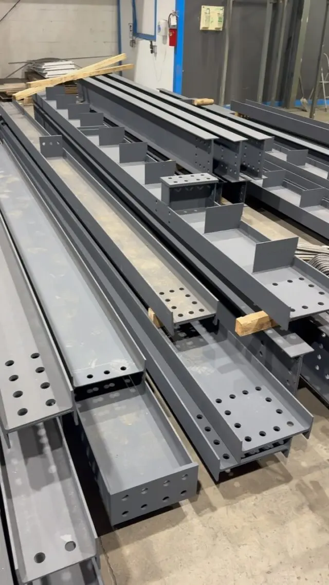
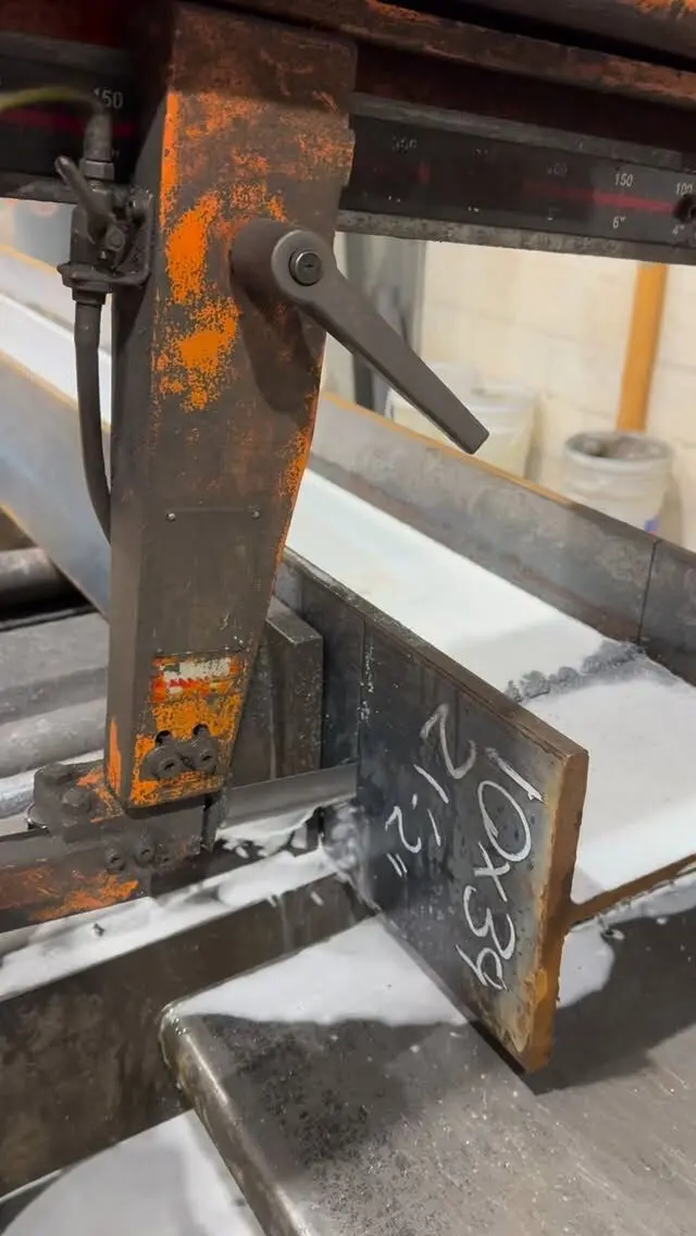
A steel beam shop drawing shows one member with every dimension needed to make it: section and length, end cuts and copes, hole locations, plates, stiffeners and welds, camber and piece mark. To produce it, the fabricator needs more than a beam size. It needs the member's location and elevation, how each end connects, who designs those connections, any camber or finish, and on renovation work, dimensions measured on site. Missing any of those is the most common reason steel sits waiting for answers.
This post covers what goes on beam and column details and what to give your fabricator. For the full drawing set and its title blocks, notes and numbering, see what to include in a steel shop drawing.
What a beam detail shows
A beam detail (also called a piece drawing or single-part drawing) usually shows the member in elevation, with a top or bottom view and end views where needed. Expect to find:
- Piece mark and quantity. The mark is painted or stamped on the steel and matches the erection drawing, so the crew knows where it goes.
- Section and grade. For example W310x39 in 350W or a dual-certified grade, as the design specifies.
- Overall length and end preparation. Square cuts, bevels or copes at each end.
- Copes and blocks. The cut-outs that let a beam's flange clear the flange of the member it frames into, dimensioned by depth and length.
- Hole groups. Located along the beam (from a reference end) and across the flange or web (the gauge), with the spacing between holes in a row (the pitch), hole size and edge distances.
- Plates, angles and stiffeners. Shear tabs, clip angles, end plates, bearing plates and stiffeners, each with its own size and location.
- Welds. Shown with standard welding symbols giving type, size, length and whether the weld is made in the shop or the field.
- Camber. Amount and direction, where the design calls for it.
- Finish. Primer, paint system or bare steel, and areas to keep clear of paint, such as faying surfaces of slip-critical joints or faces to be field welded.
- Bill of material. Each part, its size and weight.
How the dimensions are set out
Good beam details use a consistent system so the shop can measure without adding up numbers:
- Running dimensions from one reference end. Each hole group is located from the same end of the beam, so a small error in one dimension doesn't carry into the next.
- Gauge and pitch within each group. Holes are dimensioned to each other inside the group, and the group to the reference end.
- Working points and centre lines for skewed or sloped members, so the geometry can be checked against the erection drawing.
- Top of steel references. The detail itself is about the piece; the erection drawing gives the top of steel elevation, and the two must agree.
Nothing on a shop drawing should need scaling. If a dimension can only be found by measuring the drawing, it is missing.
What a column detail shows
Columns carry more information per piece than beams, because they collect everything that frames into them.
- Section and length, measured from a defined reference, usually the underside of the base plate.
- Base plate: thickness, plan size, anchor rod hole pattern and hole size, and the weld to the column. Plate size and thickness come from the design.
- Cap plate or splice: top plate for a beam bearing on the column, or splice plates and holes where the column continues.
- Beam connections: the elevation of every shear tab, seat or moment connection, measured from the same reference, and its orientation.
- Orientation marks showing which face is north or which face points to a given grid line, so the column isn't set rotated.
Anchor rods are usually set by the concrete contractor from a separate anchor rod plan, so the base plate holes, the anchor rod plan and the field-set rods all have to agree. Shim and grout space under the plate is part of the elevation chain.
For a basement post, a "column detail" may be as simple as an HSS with a base and cap plate, a length and a hole pattern. The same rule applies: the length and plates come from the design and the site, not from a guess.
What the fabricator needs from you
The shop can only detail what it is given. These are the inputs that make a beam or column detail possible.
| Input | Why it matters |
|---|---|
| Member sizes and grade | Sets the section and material ordered |
| Grids, dimensions and working points | Locates every member in plan |
| Top of steel elevations | Sets connection heights on columns and relative beam heights |
| Connection design, or the forces to design them | Decides plates, bolts and welds at every end |
| Camber requirements | Some beams are ordered or cambered before detailing |
| Finish and fire protection | Primer, paint, galvanizing or bare steel for fireproofing |
| Bolt type and any slip-critical joints | Changes hole and surface preparation |
| Embedded items and supporting construction | Bearing on concrete, masonry or wood, embed plates, anchor rods |
| Revision status of the drawings | Detailing from a superseded set means rework |
Connection responsibility is the question to settle first. On many commercial jobs the engineer of record shows member sizes and forces and the fabricator's connection engineer designs the connections; on others every connection is detailed on the design drawings. If nobody has decided, detailing stalls. Our post on steel detailing services covers the options, and types of structural steel connections explains what you might see.
Residential and renovation beams
Homeowner and small-contractor jobs usually come without a full drawing set. To detail a basement beam or a beam for a removed wall, the fabricator needs:
- the beam and post sizes from the engineer or designer (the building permit drawings),
- measured clear span and bearing at each end, including what the beam sits on,
- post heights from the top of the footing or slab to the underside of the beam,
- how joists or walls connect to the beam, and whether it is flush or dropped,
- site access, since that can decide whether the beam is spliced into pieces.
The fabricator does not size the beam for you. Structural work like this needs a designer or engineer and usually a permit. Our steel beam quote checklist has a template you can copy.
Approval, revisions and what slows fabrication
Shop drawings go out for review before fabrication. The reviewer checks them against the design intent; the contractor checks them against site conditions and other trades. Returned drawings come back approved, approved as noted, or revise and resubmit. Our guide to reviewing steel shop drawings walks through what to check.
What typically holds steel up at this stage:
- Missing elevations or conflicts between architectural and structural sets.
- "Verify in field" dimensions that nobody has verified.
- Undecided connection responsibility or missing reactions.
- Late changes made on the design drawings without a revision cloud or note.
- Camber or finish not specified, found after material is ordered.
- Unanswered RFIs. Each open question on a detail is a piece that can't be cut.
The quickest projects are the ones where the questions are answered before detailing starts. If you're not sure what's missing, send what you have and ask.
Shop drawings done in-house
We prepare shop drawings in-house, then cut, fit, weld and mark every piece to match them, so the mark on the steel is the mark on the erection drawing. Our welding is CWB certified, and engineering services are available for projects that need them. We fabricate beams, columns, posts, plates and connections and deliver across the GTA and Ontario.
Send your drawings or site measurements for a free take-off and quote, or see our fabrication and shop drawing services.
Frequently asked questions
What dimensions are on a steel beam shop drawing?
The section size and length, the end cuts and copes, every hole group located along the beam and across the flange or web, the size and position of plates and stiffeners with their welds, any camber, and the piece mark. The aim is that the shop never has to scale or calculate a dimension.
What is a steel column detail drawing?
It is the shop drawing for one column: the section and length, the base plate and anchor rod holes, the cap plate or splice, and the location of every beam connection measured from a reference such as the underside of the base plate.
Who designs the connections on steel shop drawings?
Either the building's engineer of record or a connection engineer working for the fabricator, depending on the contract. The design drawings or specification should say which, and give the forces if connection design is delegated.
Can a fabricator detail a beam from a homeowner's sketch?
Only if the sketch is backed by an engineer's or designer's beam size and the real site dimensions. The fabricator details what the design calls for; it does not choose the beam size for a permit job.