To review steel shop drawings, work through them in the order the steel is built and erected: anchor bolt drawings first, then erection drawings, then the assembly drawing for each piece, checking every item against the current structural and architectural drawings. The review confirms that the detailer has interpreted the design correctly and that the steel will fit what is being built around it. It does not redesign the structure, and it does not take responsibility for dimensions away from the fabricator.
This checklist is written for general contractors, owners' representatives and design reviewers. For background on what each drawing in the package is, see shop drawings vs fabrication drawings.
Set up the review
A shop drawing review is only as good as the documents beside it. Before you open the first sheet, collect:
- The specification section for structural steel, usually in Division 05 (commonly Section 05 12 00), and the submittal procedures in Section 01 33 00. The steel section often lists what the shop drawings must show, such as fasteners, connections, member sizes and weld symbols with weld lengths.
- The current issued-for-construction structural and architectural drawings, plus addenda, bulletins and site instructions.
- The connection design, if connections were delegated to the fabricator's engineer. Check the specification for whether the connection engineer's seal or calculations are required with the submittal.
- Site information: as-built anchor bolt surveys, measured openings on renovations, and the concrete and masonry elevations as actually built.
- Other trades' shop drawings where steel supports their work: elevators, mechanical units, cladding, stairs and railings.
Then check the transmittal: which drawings are included, which are still to come, and which revisions of the design documents the detailer worked from. If the structural drawings have been revised since, say so before reviewing a single member.
Checklist 1: anchor bolt and embed drawings
These come first because the concrete trade needs them before the steel exists.
- Anchor rod diameter, grade, length, projection above concrete and embedment match the design.
- Rod patterns match the base plate holes on the column assembly drawings.
- Rod locations are dimensioned from grid lines, not just from each other.
- Top of concrete and top of grout (base plate underside) elevations are shown and agree with the structural drawings.
- Embedded plates for beams, lintels and supports bearing on concrete are located and sized.
- Any conflict with rebar, sleeves or pilasters is flagged.
Our post on column base plate design covers the details behind these items.
Checklist 2: erection drawings
Erection drawings are the map. Check them against the framing plans one bay at a time:
- Every member on the structural plans appears with a piece mark, and no piece is shown that is not in the design.
- Member sizes match the design, including members that differ from the typical size in that area.
- Top of steel elevations match, including steps, slopes and depressed areas.
- Column splice locations and heights match the column schedule.
- Bracing members, their configuration and work points match the elevations.
- Orientation is clear, for example which end of an asymmetric beam goes to which grid.
- Erection notes cover sequence, temporary bracing responsibility and field welds.
- Camber is noted where the design calls for it.
Checklist 3: assembly drawings for each piece
This is where most time goes. Sample methodically rather than at random: check every unique piece and a selection of repeats.
Main member
- Section size and grade match the design.
- Length makes sense for the grid dimension less the column or support depth and clearances.
- Copes, blocks and cuts leave enough material, and match the connection detail.
- Camber is shown with the amount and direction where required.
Connections
- Connection type matches the design: shear tab, clip angles, end plate, seat, moment connection.
- Bolt diameter, grade and number match, and the installation type (snug-tight, pretensioned or slip-critical) is noted.
- Hole types match what the design allows: standard, oversized or slotted.
- Weld types, sizes and lengths are shown with standard weld symbols, and field welds are flagged.
- Delegated connections match the connection engineer's design, and the reactions used are the ones on the structural drawings.
Fittings and finish
- Stiffeners, doubler plates and bearing plates are included where the design shows them.
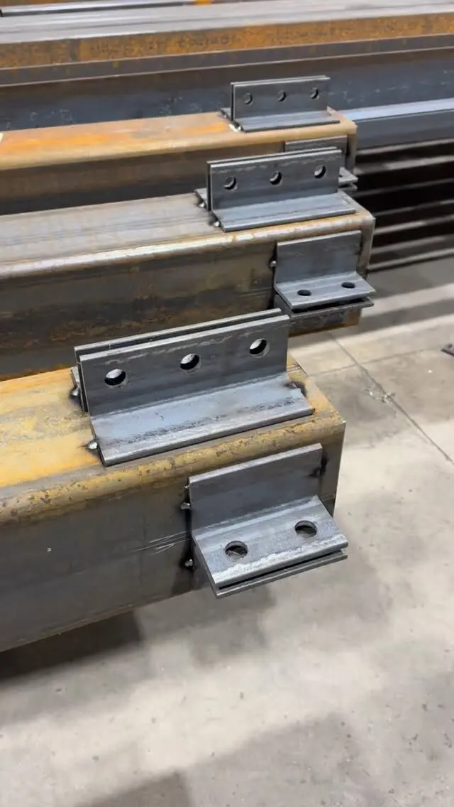
- Clips, holes and plates for other trades are present (deck support angles, cladding girts, mechanical supports, railing attachments). Adding them in the shop is far cheaper than drilling or welding on site.
- Finish matches the specification: primer, paint system, galvanizing, or bare steel where fireproofing or slip-critical faying surfaces call for it.
- The bill of materials agrees with the drawing views.
Checklist 4: coordination and site fit
The engineer reviews design intent. The contractor is often the only reviewer who knows the site. Check:
- Bearing on concrete and masonry. Bearing elevations, bearing plate sizes and the actual wall or pier dimensions agree. See steel beam bearing length on concrete and masonry.
- Existing structure. On renovations and additions, dimensions come from site measurements, not old drawings.
- Openings and clearances. Steel does not clash with ducts, sprinkler mains, stairs or elevator shafts.
- Access for erection. Connections can be bolted or welded where they sit, and pieces can be delivered and lifted at the sizes shown.
- Fireproofing and finishes. Steel exposed in the finished building may need a different finish from concealed steel.
Marking up, stamps and turnaround
How you return the drawings matters as much as what you find.
- Cloud and number every comment on the drawing itself, and keep comments specific enough that the detailer can act without a phone call.
- Answer the detailer's questions. Open items flagged on the drawings stay open until someone answers them.
- Use the review status correctly. Typical stamps read reviewed, reviewed as noted, or revise and resubmit. Reviewed as noted lets the fabricator proceed with the corrections; revise and resubmit sends the drawing round again and holds fabrication.
- Do not change the design on a shop drawing. If the design needs to change, the engineer issues a revised drawing or site instruction so everyone works from the same record.
- Understand what the stamp means. Review stamps usually state that review is for general conformance with the design concept only, and that the contractor and fabricator remain responsible for dimensions, quantities, fabrication methods and coordination. A review stamp is also different from an engineer's seal; see do shop drawings need an engineer's stamp in Ontario.
- Track turnaround. Log when each submittal went out and when it is due back. Anchor bolt drawings and the first bays of framing usually set the pace for the whole job.
Get shop drawings that review cleanly
Procut prepares shop drawings in-house from your structural and architectural drawings, then fabricates and marks every piece to match them, with CWB certified welding in our shop. Engineering services are available for projects that need them, so ask us how connection design will be handled on yours.
Send your drawings for a free take-off and quote, or see our shop drawing, fabrication and installation services.
Frequently asked questions
How do you review structural steel shop drawings?
Review them in the order they are used: anchor bolt drawings first, then erection drawings, then assembly drawings for each piece. Check every item against the current structural and architectural drawings, confirm connections match the design or the delegated connection design, and mark up anything that does not fit site conditions.
Who is responsible for checking steel shop drawings?
The fabricator and detailer are responsible for the accuracy of the drawings. The general contractor checks them for site conditions and coordination, and the engineer of record and architect review them for general conformance with the design. Review does not move responsibility for dimensions and fit away from the fabricator.
What does reviewed as noted mean on shop drawings?
It means the reviewer accepts the drawing provided the marked corrections are made. Fabrication can usually proceed with the corrections picked up, without another full review cycle, unless the project specification says otherwise.
What spec section covers structural steel shop drawings?
On most Canadian projects structural steel is specified in Division 05, commonly Section 05 12 00, Structural Steel, and the submittal process is in Section 01 33 00, Submittal Procedures. Your project specification's table of contents will confirm the exact number.