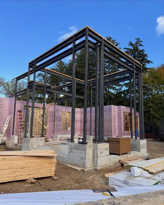
A steel column base plate is designed in two checks: the concrete under the plate must be able to take the bearing pressure (to CSA A23.3), and the plate must be thick enough not to bend where it projects past the column (with the steel resistance factor of 0.90 used in CSA S16). The worked example below sizes a plate for a square HSS post, step by step, so you can see where the dimensions on your drawings come from.
This is an illustration of the method, not a design. Real base plates are designed by the engineer of record, who also handles anchor rods, shear, uplift and the footing.
What a base plate has to do
The base plate spreads the column load over enough concrete to keep bearing stresses safe. It also gives the column something to bolt down with, through anchor rods cast into the footing or pier. Depending on the structure, it may have to carry:
- Axial compression, the main load for most building columns.
- Shear, from wind, seismic or bracing forces, carried by friction, the anchor rods or a shear lug.
- Uplift, from wind on light roofs, canopies and braced frames, carried by the anchor rods.
- Moment, when the base is designed as fixed, such as a cantilevered post or a frame without bracing.
Most building columns with four anchor rods are designed as pinned bases: they carry axial load and shear, but no significant moment. That's the case worked here. Fixed bases follow the same ideas with a non-uniform bearing pressure and tension in the rods, and they're well beyond a simple hand check.
Which standards apply
In Ontario, the 2024 Building Code (Division B, Article 4.3.4.1) requires structural steel to conform to CSA S16, and concrete to CSA A23.3. A base plate sits right where the two meet:
- CSA S16 governs the steel plate, the welds to the column and the steel side of the anchor rods. Its resistance factor for steel, φ, is 0.90.
- CSA A23.3 governs the concrete: the bearing resistance under the plate (Clause 10.8.1 in recent editions) and the anchorage of the rods in the concrete.
Neither standard gives a one-line formula for plate thickness. Designers use established methods, such as the equivalent cantilever, yield line and effective width approaches, which the CISC teaches for column bases under S16. The cantilever method is the simplest and is the one shown here. For a broader map of the codes, see Canadian structural steel codes.
Worked example: HSS post on a concrete footing
Given:
- Column: HSS 127x127x6.4, Grade 350W (127 mm square).
- Factored axial load from the engineer's analysis: Pf = 400 kN (compression, no uplift or moment).
- Trial plate: 250 mm x 250 mm, CSA G40.21 350W, Fy = 350 MPa.
- Plate centred on a concrete footing much wider than the plate on all sides, f'c = 25 MPa.
Step 1: Check concrete bearing
CSA A23.3 limits the factored bearing resistance of concrete to 0.85 φc f'c A1, where φc = 0.65 and A1 is the loaded area. When the supporting surface is wider than the loaded area on all sides, that value may be multiplied by √(A2/A1), but not by more than 2.
- A1 = 250 x 250 = 62,500 mm²
- Basic resistance: 0.85 x 0.65 x 25 MPa x 62,500 mm² = 863 kN
- With the confinement increase (capped at 2): 2 x 863 = 1,727 kN
Either way, the concrete resistance is well above 400 kN. Bearing is fine. (If the plate sits on a grout pad, the grout has to be specified strong enough too.)
Step 2: Find the bearing pressure under the plate
Assume the pressure is spread evenly under the plate:
fp = Pf / (B x N) = 400,000 N / 62,500 mm² = 6.4 MPa
Step 3: Find the cantilever length
The plate bends like a short cantilever around the column. A common convention puts the critical section slightly inside the column face, at 0.95 times the column width, which is a little conservative:
m = (N − 0.95 x d) / 2 = (250 − 0.95 x 127) / 2 = 64.7 mm
The column is square and the plate is square, so the cantilever is the same in both directions.
Step 4: Size the plate thickness
Take a 1 mm wide strip of the cantilever. The factored moment at the critical section is fp x m² / 2. The plate's factored plastic moment resistance per millimetre of width is φ x Fy x t² / 4. Setting them equal and solving for t:
t = m x √(2 x fp / (φ x Fy))
t = 64.7 x √(2 x 6.4 / (0.90 x 350)) = 64.7 x √(0.0406) = 13.0 mm
Step 5: Pick a standard thickness
Plate comes in standard thicknesses, and 13.0 mm is just over 12.7 mm (1/2 in). The next common size up is 15.9 mm (5/8 in), so the trial answer is a 250 x 250 x 16 mm plate.
| Item | Value |
|---|---|
| Concrete bearing resistance (with increase) | 1,727 kN, greater than 400 kN |
| Bearing pressure fp | 6.4 MPa |
| Cantilever m | 64.7 mm |
| Required thickness | 13.0 mm |
| Plate selected | 250 x 250 x 16 mm, 350W |
What changes the answer
A few variables move plate thickness much more than people expect:
- Cantilever length dominates. Thickness scales directly with m. Shrink the same example to a 200 mm plate and fp rises to 10 MPa, but m drops to 39.7 mm, and the required thickness falls to about 10 mm. The catch: a 200 mm plate leaves only about 36 mm on each side of a 127 mm tube, which is usually too tight for anchor rods with proper edge distance and room for nuts and washers. Anchor rod layout often sets plate size, and plate size then sets thickness.
- Steel grade. The same 250 mm plate in a 300 MPa grade needs about 14.1 mm, which still rounds to 16 mm here but won't always.
- Load. Thickness goes up with the square root of the bearing pressure, so doubling the load raises it by about 41%.
- Moment and uplift. As soon as the base carries moment or uplift, the plate bends between the rods as well as around the column, and the rods, welds and footing all need checking. That's when engineers reach for thicker plates, more rods or stiffeners.
Detailing that makes base plates work on site
The calculation is the easy part. Most base plate problems in the field come from details:
- Anchor rods and holes. Base plate holes are made larger than the rods so the column can be set despite small placement errors in the concrete. Plate washers then go over the oversized holes. Rod size, embedment and edge distances come from the engineer, with the anchorage designed to CSA A23.3.
- Levelling. Columns are set on levelling nuts, steel shims or a setting plate, then the gap is filled with non-shrink grout. The drawings should show which.
- Stiffeners. Gussets between the column and plate can reduce thickness under moment, but they add cutting, fitting and welding. For simple pinned bases, a thicker plate is usually cheaper to make.
- Welds. The column-to-plate weld size is shown on the drawings. Shop welding is done under CWB certification.
- Corrosion. Plates on exterior piers or in wet basements need a coating that suits the exposure, and a grout pad that sheds water away from the steel.
For basement posts in houses, Part 9 has its own minimums: steel columns need bearing plates at each end of at least 100 mm x 100 mm x 6.35 mm (Article 9.17.3.2 of the 2024 OBC), and the column must be centred on a footing. For whether to plate a post or cast it into concrete, see embedding steel posts in concrete vs base plates.
Getting base plates and posts fabricated
We cut, drill and weld base plates, cap plates and connection plates to your details, and supply HSS and steel posts with plates welded on. Send the engineer's base plate schedule or the details from your drawings, and we'll quote the plates, posts and connections together. If you're comparing options, see what drives base plate cost, or our HSS size chart for post sections.
Need a design, not just fabrication? Engineering services are available for projects that need them; tell us about your project when you ask for a quote. Send your drawings for a quote, or see the services we offer.
Frequently asked questions
How thick should a base plate be?
It depends on the column load, the plate size and the steel grade. For engineered columns the thickness comes from a bending check on the part of the plate that projects past the column. For Part 9 house columns, the Ontario Building Code sets a minimum end plate of 100 mm x 100 mm x 6.35 mm.
How do you calculate base plate thickness?
A common method treats the plate outside the column as a cantilever loaded by the bearing pressure from the concrete. The required thickness is the cantilever length times the square root of 2 x bearing pressure / (0.90 x yield strength), using factored loads.
Do base plates need stiffeners?
Usually not for axially loaded columns. Stiffeners are used when moments or large uplift forces would otherwise need a very thick plate. They add fabrication and welding, so engineers often prefer a thicker plate.
Is a base plate connection pinned or fixed?
A typical four-rod base plate is usually designed as pinned. A fixed (moment) base needs a thicker plate, stronger anchor rods and a footing designed for the moment, and the engineer has to design it that way on purpose.