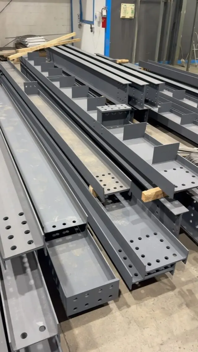
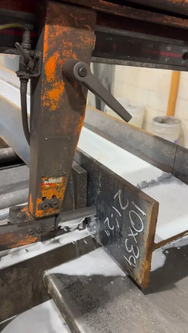
A steel shop drawing has to give the shop everything needed to make one piece without asking a question: member size and grade, exact length and cuts, every hole, plate, bolt and weld, any camber, the finish, and the piece mark that ties it to the erection drawing. Around that sits a title block, general notes, a material list and a revision history. If any of those are missing, the shop either stops to ask or guesses, and guessing is how steel arrives on site wrong.
This post walks through what belongs on a steel shop drawing, part by part. If you are new to the term, start with our explanation of shop drawings vs fabrication drawings; if you are about to review a set, use our steel shop drawing review checklist.
The title block
The title block is the drawing's identity. On a big job there may be hundreds of sheets, and the title block is how everyone finds the right one and knows whether it is current. A complete title block includes:
- Project name and address, and usually the owner or general contractor.
- Fabricator and detailer names, and contact information.
- Drawing number and title, for example a sheet numbered within the erection or assembly series and titled with the member or area it covers.
- Scale, or "not to scale" where views are schematic.
- Date, drawn by and checked by. A second set of eyes before submission is normal practice.
- Current revision number or letter, matching the revision block.
- Status, such as issued for review, reviewed, or issued for fabrication.
- Space for review stamps from the engineer of record, architect or contractor.
On a submittal set, the title block or the general notes should also list the design drawings and revisions the detailing was based on. That one line saves a lot of arguing later, because it shows exactly which version of the design the detailer worked from.
General notes
General notes cover everything that applies across the drawing set, so it does not have to be repeated on every piece. They usually sit on the first sheet of the set or on a dedicated notes sheet. Typical shop drawing general notes include:
- Materials. The specification and grade for each kind of material: wide-flange shapes, HSS, channels and angles, and plate. In Canada, W-shapes are commonly supplied to ASTM A992, often dual-certified to CSA G40.21 350W, but the grades come from the engineer's drawings and specification.
- Bolts. Bolt type and grade (for example ASTM F3125 Grade A325), hole type, and how the bolts are installed, such as snug-tight or pretensioned, as the design requires.
- Welding. The welding standard (CSA W59 for structural steel designed to CSA S16) and the requirement that welding be done by a company certified by the Canadian Welding Bureau.
- Surface preparation and finish. Primer, paint system, galvanizing, or "no paint" for surfaces that will be fireproofed or encased, as the specification calls for.
- Governing standards. CSA S16 for design and, where the contract references it, the CISC Code of Standard Practice for Structural Steel.
- Units and conventions. Dimensions in millimetres, elevations relative to a stated datum, and "do not scale drawings".
- Assumptions and open items. Anything the detailer had to assume, flagged for the reviewer to confirm.
Notes that apply to one piece only belong on that piece's sheet, close to the view they affect.
Views, dimensions and member information
This is the body of the drawing, the part the fitter works from. For each assembly, a shop drawing typically shows:
- Member designation, such as W310x39 or HSS152x152x9.5, with the grade if it differs from the general notes.
- Overall length and the dimensions that set it: cut length, end cuts, copes, blocks and any bevels.
- Working points and reference lines, so dimensions build from consistent points rather than from edges that may vary.
- Hole locations and sizes, dimensioned from a reference end and from the flange or web, with gauges.
- Plates and fittings shown in place, with their part marks, and located on the member.
- Camber, if the design calls for it, as a midspan dimension with its direction.
- Orientation, so the piece cannot be installed backwards or upside down. A note or symbol showing which end or face goes where is cheap insurance.
- Sections and detail views at connections, wherever a plan or elevation does not show enough.
Dimensions are given so the shop never has to add up a chain to find a hole. Running dimensions from one end, with key overalls, keep errors from stacking. Our post on steel beam shop drawings goes deeper on what a single beam drawing needs.
Connection details: plates, bolts and welds
Connections are where most of the information on a shop drawing lives, and where most review comments land. A complete connection detail shows:
- Every plate with its thickness, size, part mark, and its hole pattern.
- Bolts by size, quantity and grade, and whether they are installed in the shop or the field.
- Welds with standard welding symbols: type, size, length, which side, and whether the weld is made in the shop or the field. The field weld flag on the symbol tells the erector it is their weld.
- Clearances and erection tolerances where pieces meet, so the piece can be swung into place.
Who designs the connections depends on the contract. On some projects the engineer of record details every connection. On many Canadian projects, the fabricator's engineer designs connections to forces given on the structural drawings, and those designs go in with the shop drawings for review. The shop drawing has to show the result either way. Whether that work carries a professional seal is a separate question, covered in our post on whether shop drawings need an engineer's stamp in Ontario.
Material lists and the shop drawing numbering system
Bill of materials
Each assembly drawing carries a material list: every part, with its mark, quantity, size or section, length, grade and often weight. The shop uses it to pull stock and cut parts; estimators and project managers use the summed weights to track tonnage. Bolts are usually listed separately, either per drawing or in a bolt list for the whole job, split into shop and field bolts.
Numbering and piece marks
A shop drawing numbering system ties three things together: the drawing sheets, the shipping pieces, and the parts inside them.
- Drawing numbers follow a series, with erection drawings, assembly drawings and part drawings usually numbered separately so a sheet's type is obvious from its number.
- Assembly marks (also called erection marks or shipping marks) identify each shipping piece. They appear on the assembly drawing, on the erection drawing showing where it goes, and on the steel itself. Many detailers use a letter prefix for the member type, such as B for beams and C for columns, but the convention varies by shop.
- Part marks (piece marks) identify individual plates, angles and fittings within an assembly.
The rule that makes it work is simple: identical pieces share a mark, and anything different gets its own, even if the only difference is one hole or a handed (mirror-image) plate. Two beams that look the same but are not, sharing one mark, is a classic way to end up with a beam that will not fit.
Revision block and clouds
Every change after the first issue gets a new revision number or letter, a dated entry in the revision block describing what changed, and a cloud around the change on the drawing. The shop only builds from the current issued-for-fabrication revision, and superseded prints come off the floor.
Small jobs and residential steel
A single basement beam does not need a 40-sheet submittal, but it still needs a drawing with the same core content: beam size, length, end conditions, bearing plates, holes for posts or connections, any camber, the finish, and a mark. On small jobs that is often one sheet, prepared from the designer's permit drawing and site measurements. If the permit drawing is light on detail, our guide on what to send for a steel beam quote lists what helps.
Getting shop drawings prepared
We prepare shop drawings in-house from your structural or architectural drawings, then fabricate to them, with CWB certified welding and every piece marked to match the drawings so it goes up quickly on site. Engineering services are available for projects that need them, and take-offs and quotes are free.
Send us your drawings for a quote, or see our shop drawing, fabrication and installation services.
Frequently asked questions
What do shop drawings include?
A steel shop drawing shows one shipping piece or assembly with its member size, length, cuts, holes, plates, bolts, welds, camber and piece mark, plus a title block, general notes, a material list and a revision history. Erection drawings in the same package show where each piece goes.
What goes in a shop drawing title block?
The project name and location, the fabricator, the drawing number and title, scale, date, who drew and checked it, the current revision, the status (such as issued for review or issued for fabrication) and space for the review stamp.
What are typical shop drawing general notes?
Material specifications for each kind of shape and plate, bolt type and installation, the welding standard and certification, surface preparation and finish, units, the governing design and practice standards, and a list of the design drawings and revisions the detailing is based on.
How are steel shop drawings numbered?
Each sheet has a drawing number, and each piece has a mark. Assembly or erection marks identify shipping pieces and appear on the erection drawings and on the steel itself; part or piece marks identify the individual plates and fittings. Identical pieces share a mark; anything that differs, even by a hole, gets its own.