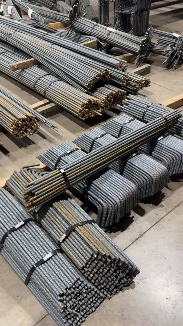
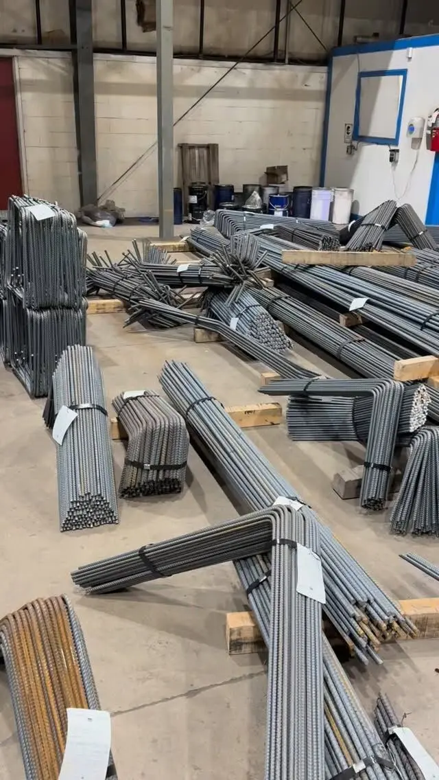
Rebar detailing for beams and columns turns the engineer's beam and column schedules into bar marks, bend shapes and placing instructions. The detailer sizes the stirrups and ties, works out how bottom and top bars anchor at supports, offset bends the column bars for splices, and lays out crossties so every bar the code requires is held in place. Most of those choices follow CSA A23.3 and the defaults in the Reinforcing Steel Institute of Canada (RSIC) Manual of Standard Practice.
This post walks through how beams and columns are detailed. For the spacing rules themselves, see stirrup spacing in beams and columns, and for how bar sizes are picked, see choosing rebar sizes for beams and columns.
What the detailer starts from
A concrete frame's reinforcement normally arrives on the structural drawings as schedules and typical details:
- A beam schedule: mark, size, top bars, bottom bars, stirrup size and spacing zones, and sometimes the cut-off points.
- A column schedule: mark, size, vertical bars, tie size and spacing, and the levels where bars change.
- Typical details: how bars anchor at end supports, how laps are arranged, how ties are arranged for different bar counts, and how joints are handled.
The detailer's job is not to redesign any of that. It is to turn every line of the schedule into bars that can be cut, bent, delivered and placed, and to flag anything that doesn't fit. RSIC is clear that the engineer must specify bar lengths or cut-off locations in beams, and must show bar positions where reinforcement gets congested, such as where two beams cross or a beam meets a column.
Detailing beam reinforcement
Bottom bars and anchorage at supports
Bottom bars carry the tension at midspan. Not all of them have to run the full length, but some must reach the supports. CSA A23.3 (Clause 12.11.1 in the 2004 edition we checked) requires at least one third of the positive moment steel in simply supported members, and one quarter in continuous members, to extend along the same face into the support. In beams cast monolithically with their supports, those bars go at least 150 mm into the support. In a beam that is part of the lateral load resisting system, those bars must also be fully anchored at the face of the support.
Top bars over supports
Top bars handle the hogging over interior supports and the restraint at end supports. Their lengths come from the design. Where the engineer does not give a length, the RSIC manual sets a default: negative moment bars extend into the adjacent span to 12 bar diameters past the quarter point of the longer span. At a non-continuous end, top bars run to within 80 mm of the outer face of the supporting member and usually finish with a 90° or 180° hook to get the embedment they need.
Laps in top and bottom bars belong in specific zones. Our guide to lap length and splice zones covers where they go.
Stirrups
Unless the drawings say otherwise, RSIC practice details stirrups 80 mm less than the beam width and depth, out to out, and places the first stirrup no more than 50 mm from the face of the support. The spacing zones come from the beam schedule.
The type of stirrup matters as much as the size:
- Open stirrups (U shapes with hooks at the top) suit beams where the design allows them.
- Closed stirrups are needed where beams resist torsion or stress reversals. A23.3 accepts closed stirrups made in one piece with overlapping hooks around a longitudinal bar, or in one or two pieces joined with a Class B lap.
- Two-piece closed stirrups (a U-stirrup with a cap tie, or two lapped U-bars) are often easier to place. RSIC points out that springing a one-piece closed stirrup open to feed longitudinal bars through can crack the bar, and recommends two-piece assemblies where bars must be threaded through tight column steel.
- Edge and spandrel beams. RSIC notes that where stirrups are shown in an edge or spandrel beam, they must be closed, with a longitudinal bar in each corner at least the stirrup size and not less than 10M.
Hook angles and leg lengths come from the standard hook tables, and the detailer adds them to each stirrup mark on the bar list.
Detailing column reinforcement
Ties and crossties
Ties confine the vertical bars and stop them buckling. In A23.3 (2004 edition):
- Ties for vertical bars up to 30M must be at least 30% of the largest vertical bar diameter; for 35M and larger bars, and for bundled bars, ties must be at least 10M.
- Every corner bar and every alternate bar must be held by the corner of a tie with an included angle of not more than 135°, and no bar may be more than 150 mm clear on either side from a bar held that way.
- Crossties have a 135° hook at one end and at least a 90° hook at the other, both engaging perimeter bars, and the 90° ends of successive crossties alternate.
That 150 mm rule is what drives the tie arrangement. A 300 mm column with four bars needs one perimeter tie. A larger column with bars along each face needs either a second, smaller tie inside the first (a diamond or rectangle) or crossties, and the column schedule or typical detail shows which.
RSIC sizes column ties 80 mm less than the column dimensions, out to out, unless specified otherwise. The lowest tie starts no more than half a tie spacing above the footing or floor, and the top tie sits the same distance below the lowest horizontal reinforcement above, which matches the A23.3 rule. Where beams frame into a column from all four sides, A23.3 lets the ties stop not more than 75 mm below the lowest reinforcement in the shallowest beam.
Offset bends at splices
The search "rebar bend in column" usually means the offset bend (also called a crank) at the top of column bars. Vertical bars from the column below lap with the bars above. To keep both sets inside the ties, the lower bars are bent inward near the top so the bars above can sit where the lower bars were.
A23.3 sets the rules for offset bars:
- The slope of the inclined part must not exceed 1 in 6 relative to the column axis, with the parts above and below the bend parallel to the axis.
- Ties or spirals that provide horizontal support at the bend are placed not more than 150 mm from the bend. RSIC adds that extra ties are needed at offset bends, usually one or more at the lower bend point.
- Where the column face is offset by more than 75 mm, bars are not offset bent. Instead, the lower bars stop and separate straight dowels lap with the bars above.
RSIC detailing practice is to shop offset bend all lap-spliced verticals in square and rectangular columns. Round columns that stay the same size can usually lap without offsets, because the bars above can sit in the same circle.
Where column bars change or stop
When a column's bar arrangement changes between floors, bars from below either extend to lap with the bars above or stop just below the top of the floor, with dowels added. At a column that ends at the roof or top floor, if no termination detail is shown, RSIC practice supplies the verticals straight and stops them a short distance below the top of the slab. If your column needs the bars hooked or developed into the slab above, that has to be on the structural drawings, because the detailer will not add it by default.
Beam-column joints and congestion
The joint is where detailing gets difficult. Beam top bars from two or more directions, column verticals, offset bends, ties and sometimes slab bars all meet in one block of concrete. A23.3 requires an enclosure around reinforcement anchored in the joint, and ties within the joint where moments transfer between beams and columns, unless the joint is restrained on all four sides by beams or slabs of about equal depth. Seismic frames add much stricter hoop and tie requirements.
Good practice to reduce clashes:
- RSIC recommends that designers set beam and column widths so horizontal and vertical bars don't fall in the same plane.
- Where beams cross, the engineer should say which bars go on top; the detailer should not guess.
- Beam bars hooking into columns need their hook tails checked against the column verticals and ties.
- Sections through crowded joints at a larger scale show the crew the order of placement.
Congestion problems found on paper are cheap. Found on site, they mean field bending, cutting or a call to the engineer.
On the bar list
Once the arrangement is settled, each element becomes marks on a bar list: straight bars by length, bent bars by RSIC bend type with leg dimensions, stirrups with S-type shapes and ties with T-type shapes. Rebar bending shape codes explains the shape numbers.
If you are searching for how to bend stirrups yourself or which stirrup bender to buy, the trade-offs are in bending stirrups on site vs shop fabrication. For a frame with dozens of beams and columns, shop-bent stirrups and ties tagged by mark usually save more time than they cost.
Some quick checks before you approve beam and column placing drawings:
- Stirrup and tie sizes match the schedule, and closed stirrups appear wherever torsion or spandrel details call for them.
- Bottom bars reaching the supports meet the typical detail.
- Top bar lengths match the drawings, or the RSIC default is noted as an assumption.
- Offset bends appear where columns lap, and dowels replace them where the face steps more than 75 mm.
- Crosstie layouts hold every bar the 150 mm rule requires.
- Joint sections show the bar order where beams cross.
Getting beams and columns detailed and bent
We prepare bar lists and placing drawings for beams and columns from your structural drawings, then cut and bend the bar, including stirrups, ties, crossties and offset column bars, in sizes from 10M to 55M. Everything is tagged and bundled by mark and delivered across the GTA and Ontario.
Send us your structural drawings for a free take-off and quote, or see our detailing, fabrication and installation services.
Frequently asked questions
How are stirrups sized on a rebar detail?
Unless the drawings say otherwise, Canadian detailing practice in the RSIC manual sizes stirrups 80 mm less than the beam width and depth, measured out to out. That leaves room for cover on all sides.
Why are column bars bent at the top?
Column verticals are usually shop offset bent so they can lap beside the bars of the column above while staying inside the ties. CSA A23.3 limits the slope of the offset to 1 in 6 and requires ties near the bends.
When should column bars not be offset bent?
When the column face steps in by more than 75 mm, CSA A23.3 does not allow the bars to be offset bent. The bars below stop short and separate dowels lap with the bars above.
What is a crosstie in a column?
A crosstie is a single bar that crosses the column core to hold an interior longitudinal bar. Under CSA A23.3 it has a 135° hook at one end and at least a 90° hook at the other, and successive crossties alternate their 90° ends.