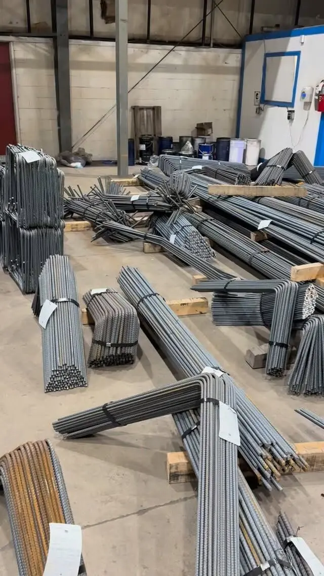
Stirrup spacing in a beam is set by the engineer from the shear the beam carries, and under CSA A23.3 it can never exceed 0.7 times the effective shear depth (dv) or 600 mm, whichever is less. Where shear or torsion is high, both limits are halved. In columns, ties are spaced at no more than the least of 16 vertical bar diameters, 48 tie diameters, or the least column dimension. The spacing on your drawings will often be closer, and seismic designs tighten it further near joints.
Stirrups in beams and ties in columns do different jobs (resisting shear, and confining the vertical bars), so their spacing rules are different. Our post on stirrup sizes and hook lengths covers the bar sizes and hooks.
When a beam needs stirrups
Not every concrete member needs stirrups. CSA A23.3 (Clause 11.2.8.1) requires at least minimum shear reinforcement in a beam:
- where the factored shear force exceeds the shear the concrete can resist on its own,
- in beams with an overall depth greater than 750 mm, and
- where factored torsion exceeds one quarter of the cracking torsion.
Where stirrups are required, they must provide at least a minimum area of steel. A23.3 sets it as Av ≥ 0.06 × √f'c × bw × s ÷ fy, where Av is the total area of the stirrup legs, bw the web width, s the spacing and fy the stirrup's yield strength. In practice this minimum rarely governs for 10M two-leg stirrups in ordinary beams: the maximum spacing limit does.
Slabs and footings usually do not get stirrups. Their thickness is chosen so the concrete alone carries the shear, and when it cannot, the designer thickens the element or adds shear reinforcement as a special detail.
Maximum stirrup spacing in beams
A23.3 Clause 11.3.8 sets the limits:
| Condition | Maximum spacing |
|---|---|
| Normal case | the lesser of 0.7 dv and 600 mm |
| High shear: Vf greater than 0.125 λ φc f'c bw dv, or Tf greater than 0.25 Tcr | half of the above: the lesser of 0.35 dv and 300 mm |
dv is the effective shear depth, taken as the greater of 0.9 d and 0.72 h, where d is the depth to the centre of the tension steel and h is the overall depth.
Worked example: a 300 mm by 500 mm beam, d about 440 mm.
- dv = the greater of 0.9 × 440 = 396 mm and 0.72 × 500 = 360 mm, so dv = 396 mm
- Normal maximum: 0.7 × 396 = 277 mm (less than 600 mm), so about 275 mm
- High-shear maximum: half of that, about 135 mm
| Beam depth (h) | Approx. d | dv | Normal max spacing | High-shear max spacing |
|---|---|---|---|---|
| 400 mm | 340 mm | 306 mm | about 210 mm | about 105 mm |
| 500 mm | 440 mm | 396 mm | about 275 mm | about 135 mm |
| 600 mm | 540 mm | 486 mm | about 340 mm | about 170 mm |
| 750 mm | 690 mm | 621 mm | about 430 mm | about 215 mm |
| 1,000 mm | 940 mm | 846 mm | about 590 mm | about 295 mm |
The 600 mm and 300 mm caps only take over in beams deeper than about 1 m. The d values assume about 60 mm from the bottom face to the centre of the tension bars, and the spacings are rounded down to a practical 5 mm. Your engineer's numbers will differ with the real cover and bar sizes, and the design spacing is often closer than these maximums. These limits are the ceiling, not the detail.
Beams commonly have zones: stirrups at close spacing near the supports, where shear is highest, opening up toward midspan. The drawings show each zone with its spacing and length, sometimes as a callout like "10M stirrups: 1 @ 50, 8 @ 150, rest @ 250 each end".
Tie spacing in columns
Column ties hold the vertical bars in position and stop them buckling outward under load. A23.3 Clause 7.6.5.2 limits their spacing to the least of:
- 16 times the diameter of the smallest vertical bar,
- 48 times the tie diameter, and
- the least dimension of the column.
For concrete stronger than 50 MPa, those values are multiplied by 0.75.
Worked examples with 10M ties (11.3 mm):
| Column | Vertical bars | 16 × bar | 48 × tie | Least dimension | Maximum tie spacing |
|---|---|---|---|---|---|
| 300 × 300 mm | 15M (16.0 mm) | 256 mm | 542 mm | 300 mm | 256 mm |
| 400 × 400 mm | 20M (19.5 mm) | 312 mm | 542 mm | 400 mm | 312 mm |
| 500 × 500 mm | 25M (25.2 mm) | 403 mm | 542 mm | 500 mm | 403 mm |
| 600 × 600 mm | 30M (29.9 mm) | 478 mm | 542 mm | 600 mm | 478 mm |
In practice these are rounded down to a convenient spacing (250, 300, 400, 450 mm). Columns also need ties arranged so that corner bars and alternate bars are held by a tie corner, which is why larger columns get extra ties or crossties inside the outer hoop. The column schedule shows the pattern.
Ties near the top and bottom of a column, at splices and at beam joints often get closer spacing, and the drawings will show those zones separately.
Seismic zones tighten spacing
Buildings designed for ductile seismic response follow the special provisions of CSA A23.3 Clause 21. Near beam-column joints and at the ends of members where plastic hinges can form, hoops and ties are spaced much closer than the general limits above, with seismic 135° hooks. The exact spacing depends on the system and the member, so take it from the drawings. Do not apply the general spacing to a zone the drawings mark as a seismic hinge region.
Counting stirrups along a beam
Once you know the spacing, the count is straightforward:
- Take the length of the zone, minus the distance to the first stirrup at each end.
- Divide by the spacing and round up to a whole number of spaces.
- Add one. The number of stirrups is always one more than the number of spaces.
Example: a 6.0 m beam with stirrups at 250 mm, first stirrup 50 mm from each support face. (6,000 minus 100) ÷ 250 = 23.6, round up to 24 spaces, so 25 stirrups. With zones, count each zone separately and do not double-count the stirrups at the zone boundaries.
Where the first stirrup sits is part of the detail. Drawings or the detailer's general notes set it, and it should not be left to the crew. Our rebar estimating guide has a full worked example including stirrup length and weight.
Getting the spacing right on site
- Mark the spacing on the main bars with paint or chalk before sliding stirrups on, especially in zoned beams.
- Tie each stirrup to the main bars at the corners so they cannot slide when concrete is placed and vibrated.
- Check the zone lengths, not just the spacing. A zone of close stirrups that stops short is a common deficiency.
- Keep spacing even through laps. Laps in the main bars do not change the stirrup spacing unless the drawings say so.
- Use the right hook. Closed stirrups and seismic hoops with the wrong hook type are a rejection item; see our ordering guide for custom stirrups.
Stirrups bent and counted for you
A detailed bar list gives you the stirrup count per zone and per beam, and shop-bent stirrups arrive tagged by mark so each bundle goes to the right beam. We prepare stirrup schedules, bar lists and placing drawings from your structural drawings, then bend and bundle stirrups, ties and crossties to match. Send us your drawings for a free take-off and quote, or see our services for detailing, cut and bend, delivery and installation.
Frequently asked questions
What is the maximum stirrup spacing in a beam?
Under CSA A23.3, stirrups can be no farther apart than 0.7 times the effective shear depth (dv) or 600 mm, whichever is less. Where shear or torsion is high, both limits are halved. The design spacing is often closer still.
What is the maximum tie spacing in a column?
CSA A23.3 limits column tie spacing to the least of 16 times the smallest vertical bar diameter, 48 times the tie diameter, and the least dimension of the column. Those limits are multiplied by 0.75 for concrete stronger than 50 MPa.
How far apart should stirrups be in a beam?
As far apart as the structural drawings show, which is set by the shear the beam carries and never more than the A23.3 maximum. For a typical 300 by 500 mm beam, the maximum works out to roughly 275 mm, and many beams are detailed closer near the supports.
Are links the same as stirrups?
Yes. Link is the British term for a stirrup or tie. In Canada, stirrups are used in beams and ties in columns, and both are spaced to CSA A23.3.