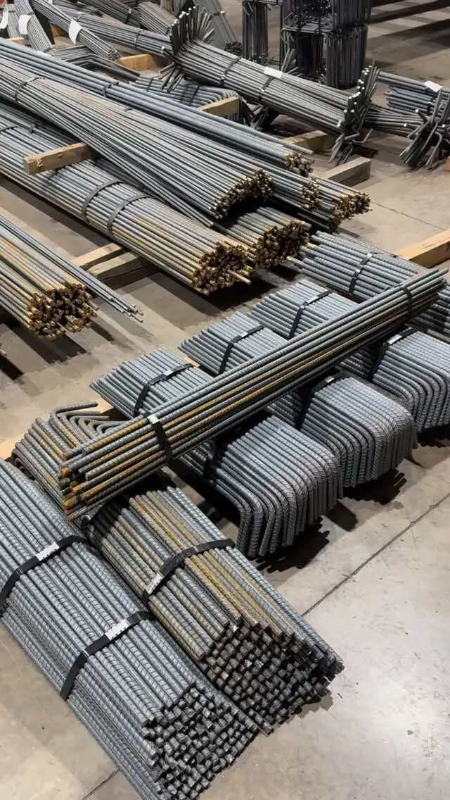
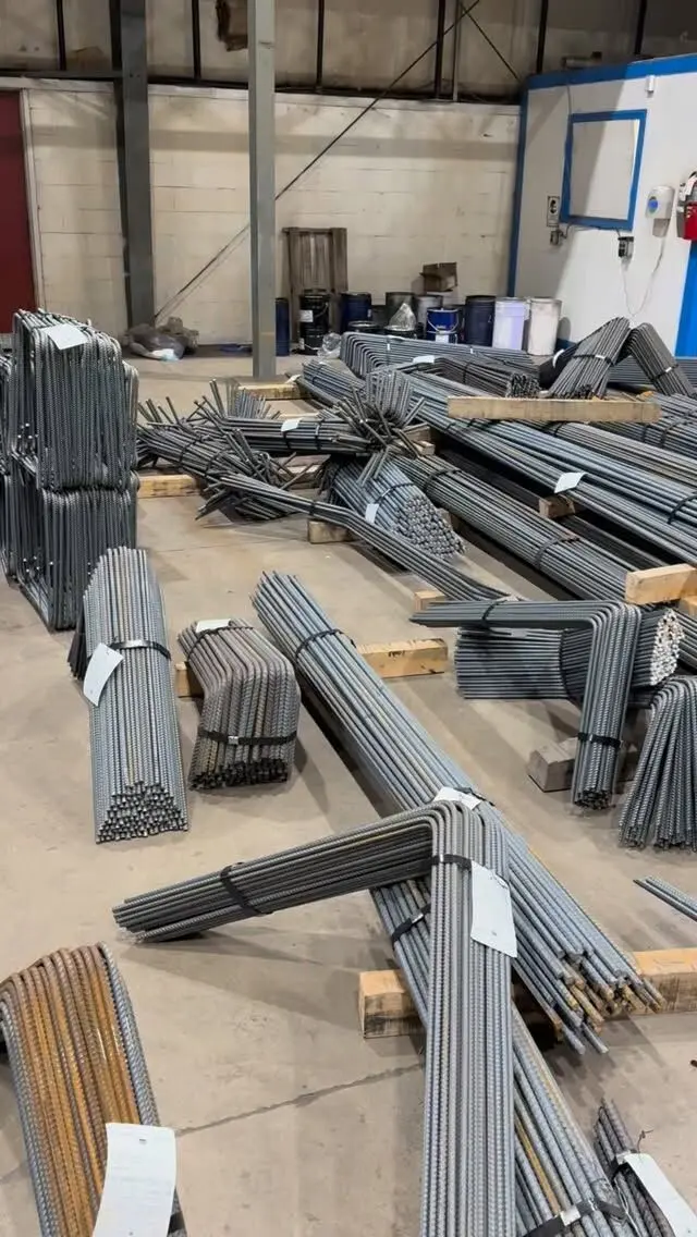
Beam and column laps in Canada are set by CSA A23.3, and where the lap goes matters as much as how long it is. A standard tension lap is a Class B splice, 1.3 times the development length and never less than 300 mm, which for Grade 400 bar in 30 MPa concrete is about 550 mm for 15M and 1,080 mm for 25M. In a typical continuous beam, top bars are lapped near midspan and bottom bars near the supports, so neither lap sits where its bar works hardest. Column bars are usually lapped just above each floor, except in seismic ductile frames, where the code pushes laps away from the column ends.
This post covers the "where" for beams and columns, with lap lengths drawn from our lap splice chart for metric bars.
Lap length: formula vs rules of thumb
Many searches for "beam steel lap length formula" or "column lapping formula" are looking for a fixed multiple like 40d or 50d. Those rules come from other countries' codes and site habits. In Canada, CSA A23.3 Clause 12 builds lap length from:
- Development length (ld), calculated from bar diameter, steel yield strength, concrete strength and modification factors for top bars, coating, concrete density and bar size.
- Splice class. Class B (1.3 ld) is the default; Class A (1.0 ld) only where the steel provided is at least twice what is required and less than half the bars are spliced in the lap length.
- Compression laps for bars only in compression, which use a separate, usually shorter expression.
Here is what that gives for typical beam and column cases (Grade 400, normal-density 30 MPa concrete, simplified method with minimum stirrups or ties through the lap, uncoated bar):
| Bar | Beam bottom bar, Class B | Beam top bar, Class B | Column, compression lap |
|---|---|---|---|
| 15M | 550 mm | 720 mm | 470 mm |
| 20M | 670 mm | 870 mm | 570 mm |
| 25M | 1,080 mm | 1,400 mm | 740 mm |
| 30M | 1,280 mm | 1,670 mm | 880 mm |
| 35M | 1,530 mm | 1,990 mm | 1,050 mm |
"Top bar" means a horizontal bar with more than 300 mm of fresh concrete cast below it, which covers the top bars in most beams deeper than about 350 mm. Compared with 40d, the calculated laps run from about 29d (column compression laps) to over 55d (25M and larger top bars). A single rule of thumb is short in some places and wasteful in others.
The lengths on the structural drawings always govern. Epoxy coating, 500W bar, lower concrete strength, bundled bars and tight cover or spacing all lengthen laps. See our guide to epoxy-coated rebar lap length for the coated case.
Where to splice beam bars
A lap is a weak point compared with a continuous bar: it relies on the concrete between the two bars and is more prone to splitting. The general principle is to splice bars where they are least stressed, and not to splice them all in the same place.
In a typical continuous beam under gravity load:
| Bars | Where they work hardest | Usual splice zone |
|---|---|---|
| Top bars | Over the supports (negative moment) | Near midspan, in the middle portion of the span |
| Bottom bars | At midspan (positive moment) | At or near the supports, often lapped over or into the column or wall |
| Side (skin) bars | Along deep beams | Wherever the drawings show, usually staggered |
Other points the drawings normally control:
- Stagger. Engineers often require laps to be staggered so not every bar is spliced at the same section. Staggering changes bar lengths, so the bar list has to follow it exactly.
- Stirrups through the lap. The shorter simplified-method laps assume minimum stirrups through the splice. A lap in a zone without stirrups needs the longer coefficient. Our post on stirrup spacing in beams and columns covers the stirrups themselves.
- Continuity into supports. A23.3 requires part of the bottom reinforcement to continue into the supports, so not all bottom bars can stop short of the column.
- Cantilevers and transfer beams reverse the usual pattern: top bars are in tension along the whole cantilever and over its support. Do not apply the midspan rule there.
Simple-span beams with no continuity, like many lintels and short headers, often avoid laps entirely by using single bars full length. With straight bar lengths limited by shipping and handling, longer beams cannot.
Where to splice column bars
Column vertical bars are almost always lapped just above each floor slab, because that is how columns are built: the bars from the column below project up through the floor, and the next lift's bars lap with them. This keeps every lift a manageable length and gives the crew a fixed reference.
What to watch:
- Offset (cranked) bars. Where the lower column's bars must shift inward to fit inside the upper column's bars, they are bent with an offset just below the lap. A23.3 limits the slope of offset bends and requires ties near the bend to resist the outward thrust. The drawings and bar list show the offset dimensions.
- Compression or tension lap. A column lap can be detailed as a compression lap only if the bars never see significant tension under any load combination. Columns in frames that resist wind or earthquake often need tension laps. That decision is the engineer's, and A23.3 has special splice requirements for columns that tie the lap type to the calculated bar stress.
- Ties through the lap. Column ties continue through the lap zone. In some cases, closer tie spacing over the lap can allow a reduced compression lap.
- Big bars. A23.3 does not permit lap splices for bars larger than 35M except in limited compression cases. 45M and 55M column bars are joined with mechanical couplers or welded splices, as covered in rebar couplers vs lap splices.
Seismic frames move the splice zones
Buildings in higher seismic zones, or any frame designed as ductile, follow CSA A23.3 Clause 21. Those rules keep lap splices out of the places where the structure is expected to yield and absorb energy in an earthquake:
- Beams: laps are kept out of beam-column joints and away from the beam ends where plastic hinges are expected, and laps that are permitted must be enclosed by closely spaced hoops.
- Columns: splices are moved away from the column ends toward mid-height, again with closely spaced confinement, instead of the usual "just above the floor" location.
The details depend on the type of frame and the clause edition the engineer is designing to, so we do not list numbers here. The practical point for contractors and detailers: if the drawings show a column lap at mid-height or a beam lap well away from the support, that is deliberate. Do not move it to the "usual" place.
Laps on bar lists and placing drawings
Most lap problems on site start on the bar list:
- Use the lap table for each element, not one length for the whole job. Beams, columns and slabs often have different concrete strengths and different splice classes.
- Mark the splice zones on the placing drawings so the ironworkers know where each lap starts and ends.
- Allow for laps in the take-off. Every lap is extra steel. Long beams and tall columns with many laps add up.
- Coordinate offsets and couplers before fabrication, because a cranked bar or a threaded end cannot be fixed on site.
Our guide to how to read rebar shop drawings shows how laps and splice zones appear on placing drawings.
Getting laps and splice zones right
We prepare bar lists and placing drawings that take lap lengths and splice zones from your structural drawings, then cut, bend, crank and tag the bars to match. Send us your drawings for a free take-off and quote, or see our rebar products for straight and fabricated bar from 10M to 55M.
Frequently asked questions
What is the lap length for beam steel?
In Canada it comes from CSA A23.3, not a fixed multiple of bar diameter. A standard Class B tension lap is 1.3 times the development length. For Grade 400 bar in 30 MPa concrete with minimum stirrups, that is about 550 mm for 15M and 1,080 mm for 25M bottom bars, and longer for top bars.
Where should beam bars be lapped?
Away from the points of highest tension. In a typical continuous beam, top bars are in tension over the supports, so they are lapped near midspan, and bottom bars are in tension at midspan, so they are lapped at or near the supports. The structural drawings show the permitted zones.
Where is the column lapping zone?
Column vertical bars are usually lapped just above each floor level, which is the easiest place to build. In ductile frames designed for earthquakes, CSA A23.3 restricts laps near the column ends, which moves them toward mid-height. Follow the drawings.
Is 50d the lap length for columns?
No. 50 bar diameters is a rule from other countries' practice, not a Canadian requirement. CSA A23.3 sets column laps as compression or tension laps depending on the loads, and the result can be shorter or longer than 50d.