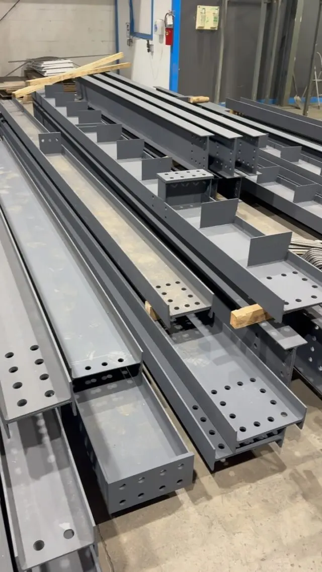
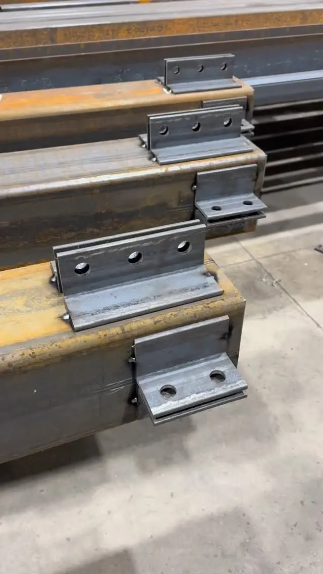
A steel I-beam has three main parts: two flanges (the horizontal plates at the top and bottom), a web (the vertical plate joining them), and its depth (the overall height from the outside of one flange to the outside of the other). The flanges carry most of the bending, the web carries most of the shear, and the depth sets how stiff and strong the beam is. Knowing the names helps when you read a drawing, compare sizes or talk to a fabricator.
This guide walks through each part of a wide-flange (W) beam, the dimension symbols you'll see in Canadian section tables, and why each one matters on a real job.
The anatomy of an I-beam
Look at the end of a W-beam and you see a capital "I" (or an "H" for the wider sections). Every part has a name:
| Part | What it is | Symbol in Canadian tables |
|---|---|---|
| Top flange | Horizontal plate along the top | |
| Bottom flange | Horizontal plate along the bottom | |
| Web | Vertical plate joining the flanges | |
| Depth | Overall height, outside of flange to outside of flange | d |
| Flange width | Width of each flange, edge to edge | b |
| Flange thickness | Thickness of each flange | t |
| Web thickness | Thickness of the web | w |
| Fillet (root radius) | Curved transition where web meets flange | |
| k distance | Outside of flange to the end of the fillet | k |
| Toe | The outer edge of a flange |
US tables use slightly different symbols for the same things, typically bf for flange width, tf for flange thickness and tw for web thickness. The physical beam is identical; only the labels change.
Here is a real section to anchor the numbers. Values are from the CISC section tables, as listed in our Canadian W-shape chart:
| Section | Depth d | Flange width b | Flange t | Web w | Mass |
|---|---|---|---|---|---|
| W200x27 (W8x18) | 207 mm | 133 mm | 8.4 mm | 5.8 mm | 26.6 kg/m |
| W250x33 (W10x22) | 258 mm | 146 mm | 9.1 mm | 6.1 mm | 32.9 kg/m |
| W310x39 (W12x26) | 310 mm | 165 mm | 9.7 mm | 5.8 mm | 38.8 kg/m |
Notice that the flanges are thicker than the web on all three. That's deliberate, and it comes from what each part does.
What the flanges do
When a beam carries load across a span, it bends. For a simply supported beam the top fibres are squeezed (compression) and the bottom fibres are stretched (tension). The bending stress is highest at the outer edges of the section and close to zero at the middle, along a line called the neutral axis.
Putting most of the steel in two flanges, as far from the neutral axis as possible, is the most efficient way to resist that bending. It's the reason I-beams are shaped the way they are. The same amount of steel arranged as a solid square bar would be much less stiff.
The flanges also matter for practical reasons:
- Bearing. The bottom flange sits on posts, walls and bearing plates. A wider flange spreads the load and gives more room for bolts. Our guide to steel beam bearing length covers how much seat a beam needs.
- Joists and decking. Floor joists often bear on the top flange, or on the bottom flange in a flush detail. Flange width sets how much bearing they get.
- Wood nailers. In houses, a wood plate is often bolted to the top flange so joists and subfloor can be fastened to it. A narrow flange leaves little room for the bolts.
- Lateral stability. The compression flange behaves like a slender column lying on its side. If nothing holds it, it can buckle sideways under load. Joists, decking or bracing that restrain the compression flange let the beam reach its full capacity. That's a design topic in its own right, covered in lateral bracing and unbraced length.
What the web does
The web connects the two flanges and holds them at a fixed distance apart, so they work together. It also carries most of the vertical shear force, which is largest near the supports.
Because the bending stress near mid-depth is low, the web can be fairly thin. That thinness has consequences:
- Concentrated loads. Where a post or another beam lands on the flange, or where the beam sits on a narrow support, the web right under that load can yield or crumple (web crippling). Designers check this and, where needed, add bearing stiffeners: plates welded between the flanges on each side of the web.
- Connections. Most beam-to-column and beam-to-beam connections bolt through the web, using shear tabs, clip angles or end plates. See types of steel beam-to-column connections for the common details.
- Holes. Because the web near mid-depth is lightly stressed in bending, it's usually the least harmful place for a hole, but "least harmful" isn't "harmless". Any hole, cope or notch in a structural beam should be approved by the engineer. Our guide to drilling and notching steel beams explains why.
Depth: the dimension that controls stiffness
Depth has the biggest influence on a beam's stiffness. The moment of inertia, the property that sets how much a beam deflects, grows roughly with the square of the distance of the flanges from the neutral axis. Make a beam deeper and it gets stiffer much faster than it gets heavier.
That's why deeper beams usually span farther for the same weight, and why a beam's depth often becomes a headroom problem in a basement. The trade-off is constant: a shallow beam needs heavier flanges to do the same job, while a deeper, lighter beam may cost less steel but take more room.
Some points about depth catch people out:
- Nominal vs actual. The number in the name is a family name, not a measurement. A W250x33 is 258 mm deep. Within the W250 family, actual depths range from about 247 mm to 266 mm in the common sizes. Use the actual depth for headroom and flush framing. Our guide on how to read steel beam sizes explains the naming.
- Heavier can be shallower. A W310x60 is 303 mm deep, shallower than a lighter W310x39 at 310 mm. The heavier sections in a family grow mostly by thickening the flanges and web.
- Clear web depth. The flat part of the web between the fillets is less than the overall depth. Connection angles and shear tabs have to fit inside it.
Fillets, k distance and toes
Rolled beams aren't made from separate plates welded together. The web and flanges are rolled as one piece, with a curved fillet where they meet. The fillet strengthens the junction but takes up space.
The k distance, measured from the outside face of the flange to the end of the fillet, matters to detailers and fabricators:
- Bolt holes and welds are kept out of the fillet zone.
- Bearing stiffeners are clipped at the corners so they don't sit on the fillet.
- Connection plates that run along the web need to start beyond the fillet.
The toe is the outer edge of a flange. Flange tips are where you'd measure flange width, and where welds on some connections finish.
S-shapes (the older "standard I-beam" profile) have sloped inside flange faces, so their flange thickness varies across the width. Modern W-shapes have flanges with parallel faces, which makes bolting and detailing simpler. The differences are explained in I-beam vs W-beam vs H-beam.
Strong axis and weak axis
Every I-beam has two bending axes:
- Strong axis (x-x): horizontal, through the middle of the web. This is how a beam is normally loaded, with the web vertical. Section tables list properties about this axis as Ix, Sx and Zx.
- Weak axis (y-y): vertical, through the middle of the web. Bending about this axis means the beam is lying flat. Properties are listed as Iy, Sy and Zy, and they're much smaller.
For a typical W-beam the strong-axis moment of inertia is many times the weak-axis value. Turn a beam on its side and it will sag far more and carry far less. That's also why columns, which can buckle in either direction, often use the wider-flanged H-shaped sections, where the two axes are closer in strength.
Same names on other shapes
The same vocabulary carries over to other steel shapes, with a few changes:
- C-channels have a web and two flanges, but only on one side, so the section isn't symmetric. See C-channel sizes.
- Angles have two legs instead of a web and flanges.
- HSS (tube) is described by outside dimensions and wall thickness. In rectangular HSS the long sides act like webs and the short sides like flanges.
Getting the right beam made
Knowing the parts of a beam makes drawings easier to follow, but the size, connections, stiffeners and holes all come from the structural design. Bring your drawings or beam schedule, and we'll take it from there: we fabricate beams with end plates, cap and bearing plates, stiffeners, holes and camber to your shop drawings in our CWB certified shop, and deliver across the GTA and Ontario.
Send your drawings for a quote, or see the steel products we fabricate.
Frequently asked questions
What is the flange of a steel beam?
The flanges are the two horizontal plates at the top and bottom of an I-shaped beam. They sit farthest from the centre of the section, so they carry most of the bending, with one flange in compression and the other in tension.
What is the web of a steel beam?
The web is the vertical plate that joins the two flanges. It holds the flanges apart at the right depth and carries most of the shear force in the beam, especially near the supports.
What is the difference between depth and flange width?
Depth is the overall height of the beam, measured from the outside of the top flange to the outside of the bottom flange. Flange width is the horizontal width of the flanges. On a W250x33, for example, the depth is 258 mm and the flange width is 146 mm.
What is the k distance on a steel beam?
The k distance is measured from the outside face of a flange to the point where the curved fillet between the flange and web ends. Detailers use it to keep holes, welds and bearing plates clear of the thick fillet zone.
Which way up does a steel beam go?
An I-beam is normally installed with the web vertical, so it bends about its strong axis. Laid flat with the web horizontal, the same beam is far weaker and more flexible.