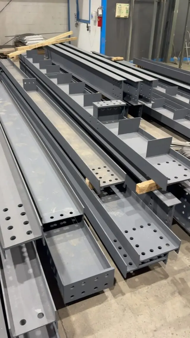
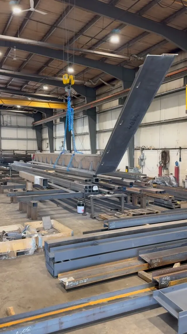
Every rolled steel beam has a little curve in it before anyone cambers it on purpose. That natural mill camber is limited by the rolling tolerances in ASTM A6/A6M, which CSA G40.20 adopts for structural shapes in Canada, and the values are summarized in the Canadian Institute of Steel Construction (CISC) Handbook of Steel Construction. Camber that the engineer specifies is a different thing: it is induced deliberately, it has its own tolerance under the fabrication standard and project specification, and that tolerance is normally on the plus side only.
This post explains the difference, where each tolerance lives, and what to put on drawings so the beams arrive the way the engineer intended. For how beams are actually cambered, see heat cambering vs cold cambering.
Camber vs sweep
Two words describe how a beam departs from straight:
- Camber is curvature in the plane of the web, measured along the depth of the section. On a beam installed web-vertical, camber is the up-or-down curve.
- Sweep is curvature in the plane of the flanges, measured along the width. On an installed beam, sweep is the sideways curve.
CISC describes both as straightness tolerances and notes that out-of-straightness limits are typically expressed as a function of member length, L. A longer beam is allowed more total deviation than a short one.
Engineers specify camber. They almost never specify sweep, which is normally just held within tolerance.
What natural mill camber is
Natural mill camber is the out-of-straightness that remains after a section is rolled, cooled and straightened at the mill. It is uncontrolled. One beam might have a few millimetres up, the next a few millimetres down, and the amount varies with size and length.
Mills straighten shapes to keep them within the rolling tolerances. One North American wide-flange producer notes in its catalogue that roll wear, deformation in the mill and the plasticity of hot steel cause variations from published dimensions, so sections may need straightening by the producer to meet camber and sweep tolerances. The same catalogue notes that tighter column tolerances apply to certain heavy sections only when they are ordered as columns.
Three practical consequences:
- Small camber may already be there. Cambering literature, including an AISC Engineering Journal paper by David Ricker, notes that small camber requirements can often be satisfied by natural mill camber.
- Columns can be ordered without it. The same paper advises that columns made from sections normally used as beams be ordered with "no camber permitted," or the mill may supply them with some natural camber.
- Orientation matters on uncambered beams. Where a beam has no specified camber, common practice is to place any natural camber upward, so the beam does not start life with a sag. Confirm how your specification handles it.
Where the camber and sweep tolerances come from
In Canada, the tolerance depends on how the member was made:
| Member | Where the straightness tolerance comes from |
|---|---|
| Rolled W, S, C and angle shapes | CSA G40.20, which refers to ASTM A6/A6M for structural shapes |
| Welded wide-flange (WWF) shapes | CSA G40.20 |
| Other welded built-up shapes | CSA W59 (CISC notes its camber requirements are essentially the same as G40.20's) |
| Hollow structural sections | CSA G40.20, or the ASTM standard the HSS is made to |
| Fabricated members and specified camber | CSA S16 fabrication tolerances and the project specification |
CISC points designers to the tolerance summary pages in its Handbook of Steel Construction, which collect the rolled, welded and HSS tolerances in one place. That is the most practical reference to keep on hand. The numeric limits depend on section size and length, so we have not reproduced them here; check the Handbook edition your engineer works to, or ask us to confirm the tolerance on a specific beam.
The fabrication side, including tolerances for length, end squareness and member straightness after fabrication, is covered in our guide to steel fabrication tolerances under CSA S16.
Specified camber and its tolerance
When the engineer calls for camber, the beam is cambered at the mill or in the fabricating shop. A few things are true of specified camber:
- The tolerance is usually plus only. Ricker's paper notes that camber tolerances are always on the plus side: a beam may arrive with a little more camber than specified, but not less. Your specification and the governing standard set the actual values.
- Some camber is lost along the way. Beams cambered at the mill lose some camber by the time they reach the fabricator, from stress relaxation, shipping vibration and how they were supported in transit. Mills often over-camber slightly to allow for it.
- Very small cambers are unreliable. The same paper notes most mills will not provide less than about 25 mm (1 in.) of camber, and recommends against cambering where less than that is needed. Fabricators can produce cambers outside the mill range by heat or cold cambering.
- Real deflection rarely matches the calculation. End connections usually provide some fixity, so beams often deflect less than predicted. That is one reason engineers often camber for only part of the calculated dead load deflection.
How camber is checked
Camber is checked in the fabricating shop, before the beam is erected. Once it is connected and loaded, its own weight, the connections and the floor build-up make the original camber hard to measure reliably.
In the shop, camber is measured as the offset at midspan from a straight line between two points near the beam ends, typically with a taut line or similar reference. A useful habit from cambering practice: describe camber as a single midspan ordinate on the drawings ("camber 30 mm"), and let the fabricator measure that same ordinate.
Sequence matters too. Cambering is usually done after the beam is cut to length and drilled. Beams that need square, parallel ends for end plates or welded moment connections are cut after cambering. The shop drawings will show the order.
When a beam is out of tolerance
If a beam arrives with too much sweep, too little specified camber, or natural camber that works against the design, talk to the fabricator and the engineer before anything is done on site. Typical fixes are done in the shop:
- Heat straightening can remove sweep or reduce camber without the risks of forcing the steel back cold. An over-cambered beam should not simply be bent back the other way in a press.
- Adding camber by heat or by a cambering machine, if the specified amount was not reached.
- Engineering review where the deviation is small and the engineer is satisfied the beam works as delivered.
Do not jack, force or flame-correct a beam in the field without the engineer's direction. That turns a fabrication question into a structural one.
What to put on your drawings
To avoid surprises with camber:
- Show specified camber for each beam that needs it, as a midspan dimension, with the direction.
- Say what the camber is for, such as a portion of dead load, so the fabricator can raise questions early.
- Mark beams that must not be cambered, such as cantilevers, moment-connected beams and beams supporting cladding, and note "no camber permitted" for columns ordered from beam sections.
- Name the tolerance or the standard the camber is checked against if your specification differs from the default.
- Leave the method to the fabricator unless there is a reason to restrict it.
If you are choosing beam sizes, our W-shape beam size chart lists common Canadian sections.
Cambered beams from our shop
We fabricate wide-flange beams with connections and camber as specified, and heat cambering of beams is one of the specialty services in our shop. Include the camber notes when you send your drawings and we will tell you how we would handle them in the quote.
Send us your structural drawings for a free take-off and quote, or see our steel products and fabrication services.
Frequently asked questions
What is natural mill camber?
It is the slight out-of-straightness about the strong axis that remains in a rolled beam after rolling, cooling and straightening at the mill. It is uncontrolled, small, and limited by the rolling tolerances in ASTM A6/A6M, which CSA G40.20 references for structural shapes.
What is the difference between camber and sweep?
Camber is curvature measured along the depth of the section, in the plane of the web. Sweep is curvature measured along the width, in the plane of the flanges. Both tolerances are expressed as a function of the member length.
Where are steel beam camber tolerances found in Canada?
For rolled shapes, CSA G40.20 refers to ASTM A6/A6M, and the CISC Handbook of Steel Construction summarizes the values. Welded shapes follow CSA G40.20 or CSA W59. Tolerances on fabricated members and specified camber come from CSA S16 and the project specification.
Is there a minimum camber for steel beams?
There is no single code minimum, but very small cambers are hard to produce reliably. Cambering literature notes most mills will not supply less than about 25 mm (1 in.) of induced camber, and small requirements can often be met by natural mill camber.