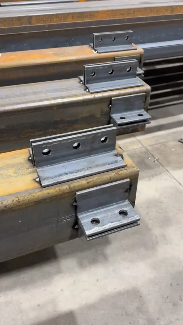
On a steel angle, the heel is the outside corner where the two legs meet, and the toes are the free edges at the end of each leg. The gauge is the distance from the heel to the centre line of a row of bolt holes, measured along the back of the leg. These three terms drive how angles are dimensioned on shop drawings: holes are set out on gauge lines from the heel so bolts clear the inside corner and keep enough edge distance to the toe.
This post explains steel angle nomenclature, how angles are noted on drawings, how gauge lines work and what to check before an angle goes to fabrication. For the available sizes, see our steel angle size chart.
Steel angle nomenclature: the parts of an angle
| Term | What it is |
|---|---|
| Leg | Each of the two flat arms of the angle |
| Heel | The outside corner, where the backs of the two legs meet |
| Toe | The free edge at the end of each leg (two per angle) |
| Back (of leg) | The outside face of a leg, the flat side that faces away from the other leg |
| Face (inside face) | The inside face of a leg |
| Fillet (root) | The rounded inside corner where the legs join, formed during rolling |
| Toe radius | The slight rounding at the toe on hot-rolled angles |
| Thickness | The leg thickness, the same for both legs on a rolled angle |
| Gauge line | A line parallel to the heel on which bolt holes are centred |
The fillet matters more than people expect. It adds a little steel at the corner (one reason the steel angle weight per metre from a table is slightly more than a simple formula), and it is the reason holes cannot be placed too close to the heel: a bolt head, nut or washer has to sit flat on the leg, clear of the curve.
Hot-rolled structural angles have a fairly sharp heel and the fillet inside. Formed angles bent from plate or sheet have a rounded heel and no fillet. Our post on steel angle vs angle iron explains how to tell them apart.
Steel angle naming convention and notation
On Canadian drawings, an angle is written as:
- L, for angle
- the two leg lengths in millimetres, longer leg first on unequal angles
- the thickness in millimetres
So L102x76x9.5 is a 102 mm by 76 mm angle, 9.5 mm thick (4 x 3 x 3/8 in). Imperial drawings write the same angle as L4x3x3/8.
Other notation you will see with angles:
- LLV and LLH. On unequal angles, "long leg vertical" or "long leg horizontal" tells you the orientation. A lintel noted L152x89x9.5 LLV has its 152 mm leg standing up.
- 2L. A pair of angles, for example 2L76x76x6.4, usually back to back.
- Back-to-back spacing. For double angles, the gap between the backs, often the thickness of the gusset plate between them.
- SLBB and LLBB. Short legs back to back or long legs back to back, for double unequal angles.
- Toes up, toes down, toes in, toes out. Orientation notes, common on lintels, ledgers and bracing.
Our posts on equal vs unequal steel angle and steel shop drawing symbols and abbreviations cover more of the shorthand.
Gauge lines: where the holes go
A gauge line (often written "gage" in North American references) is a line running the length of the angle, parallel to the heel, on which bolt holes are centred. The gauge is its distance from the heel, measured along the back of the leg.
Gauges are measured from the heel rather than the toe for a practical reason: the heel is the reference that controls fit-up. When an angle is bolted to a beam web or column flange, it is the back of the connected leg that sits against the other member, and it is the position of the holes relative to the heel that decides whether the bolts line up.
The gauge has to balance two limits:
- Clearance from the fillet. The hole must be far enough from the heel that the bolt head, nut and washer sit flat, clear of the fillet, and that a wrench or tightening tool can reach them, particularly on the leg that is not connected.
- Edge distance to the toe. The hole must be far enough from the toe to give the edge distance the design requires. Edge distance limits are set by CSA S16 and depend on bolt size and how the edge was cut.
Common arrangements:
- One gauge line on short legs: a single row of bolts.
- Two gauge lines on long legs (often called g1 and g2 in tables): two rows of bolts, either opposite each other or staggered along the length.
- Staggered holes where two rows would otherwise be too close, which affects the net section the engineer checks.
Where to find a steel angle hole gauge chart
Standard ("usual" or "workable") gauges for each leg length are tabulated in the CISC Handbook of Steel Construction and in the AISC Steel Construction Manual. These are the values detailers start from when nothing else is specified. They are not a code requirement on their own, and they are a starting point rather than an answer:
- The connection design may specify a different gauge.
- On thicker angles the flat part of the leg starts further from the heel, which can push the minimum gauge out.
- The mating member decides the final positions. A clip angle's holes must line up with the shear tab, column flange or beam web it connects to.
We have not reproduced a gauge table here because the published values should be taken from the current handbook edition your designer uses. If your drawings do not give the gauge, the shop drawings will, and the engineer reviews them.
Dimensioning angles on shop drawings
A typical shop drawing for an angle piece shows:
- the size and grade, and the length
- gauge dimensions from the heel for each row of holes, on each leg that has holes
- pitch, the spacing between holes along the gauge line, and the end distance from the cut end to the first hole
- hole size, and whether holes are standard, oversized or slotted
- any clipped toes, copes or mitred ends
- welds, if the angle is welded to another part
Clipped toes and corners are common: a toe is cut back at the end of an angle to clear a fillet weld or the fillet of the member it sits against. These show as small chamfers on the drawing.
Our post on how to review steel shop drawings covers what to check on the full set.
Common mistakes with heel, toe and gauge
- Measuring the gauge from the toe. Gauges are measured from the heel along the back. Measuring from the toe on an unequal angle or a different thickness shifts every hole.
- Mixing up the legs. On an unequal angle, holes on the wrong leg or the angle installed LLH instead of LLV changes both the fit and the strength.
- Gauge too tight to the fillet. Holes that look fine on paper can leave no room for a washer or wrench, especially on thick angles.
- Not matching the mating piece. The gauge on a clip angle must match the hole pattern on what it bolts to. Check both pieces together.
- Forgetting the outstanding leg. Bolts in one leg need clearance from the other leg for tightening, which matters on short legs and double angles.
- Orientation notes missing. "Toes down" or "toes out" on lintels and ledgers changes how water drains and how masonry or framing sits.
Angles show up throughout a building as lintels, ledgers, clip angles and bracing. Our post on clip angles and ledger angles shows how those connections use these same gauge lines.
Get your angles detailed and fabricated
We prepare shop drawings in-house and cut, punch and weld steel angles for lintels, ledgers, clips and bracing to your drawings, with CWB certified shop welding and priming or galvanizing to suit. Send your drawings through our quote request, or browse our steel products.
Frequently asked questions
What is the heel of a steel angle?
The heel is the outside corner of the angle, where the backs of the two legs meet. Bolt hole gauge lines and many dimensions on shop drawings are measured from the heel.
What is the toe of a steel angle?
The toe is the free end of a leg, the edge furthest from the heel. Each angle has two toes. The distance from the last line of holes to the toe is the edge distance on that leg.
What is the gauge of a steel angle?
The gauge (often spelled gage) is the distance from the heel, measured along the back of the leg, to the centre line of a row of bolt holes. Long legs may have two gauge lines for two rows of bolts.
Where do I find standard gauges for angle legs?
Usual or workable gauges for each leg length are tabulated in the CISC Handbook of Steel Construction and the AISC Steel Construction Manual. The values on your project come from the connection design and shop drawings, so check those first.
How do you write a steel angle size?
As L, then the two leg lengths, then the thickness: L102x76x9.5 is a 102 mm by 76 mm angle, 9.5 mm thick. On unequal angles the longer leg is written first.