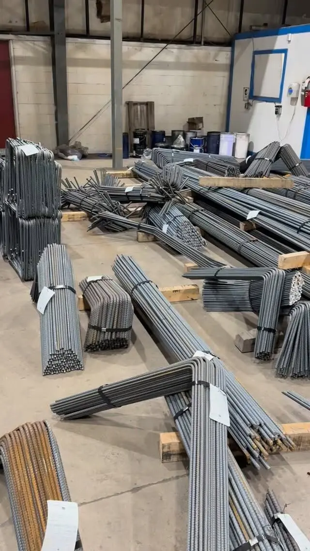
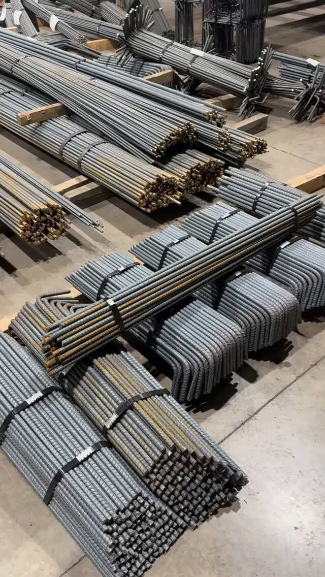
Rebar detailing for a slab turns the engineer's slab design into a bottom mat, top bars over the supports, edge and corner bars, and trim bars at openings, each with a mark, a length and a layer. The detailer works out how the bars run, where they stop and lap, how they anchor at edges, and what holds them at the right height, then puts it all on placing drawings and a bar list. The design rules come from CSA A23.3; the defaults detailers use when drawings are silent come from the RSIC Manual of Standard Practice.
This post is the detailer's view. For why suspended slabs need top and bottom steel and how one-way and two-way slabs differ, start with rebar for suspended and elevated slabs.
What goes into a slab detail
A complete slab detail answers six questions for every area of the slab:
- Which bars run in each direction, at what size and spacing.
- Which layer each set occupies, top or bottom, outer or inner.
- Where each bar starts and stops, including extensions past supports and cut-off points.
- Where bars lap, and how long the laps are.
- What happens at edges, corners, openings and columns.
- What holds the bars up until the concrete is placed.
The structural drawings give the design answers. The detailer fills in the practical ones and flags anything that conflicts. Our guide to reading slab reinforcement details covers the drawing side.
Bottom bars: the mat
The bottom mat is usually two layers of straight bars at right angles. On drawings and bar lists, layers are labelled from the outside in:
| Label | Meaning |
|---|---|
| B1 | Bottom layer, closest to the underside |
| B2 | Bottom layer, sitting on B1 |
| T1 | Top layer, closest to the top surface |
| T2 | Top layer, sitting under T1 |
The outer layer gets more effective depth, so the bars doing the most work normally go there. In a one-way slab that means the main bars run in the outer layer and the lighter distribution bars sit on them. In a two-way slab the drawings say which direction goes outermost.
Practical points detailers deal with:
- First bar location. Where bars run parallel to a supporting beam or wall, RSIC practice puts the first bar half a spacing from the support, then the rest at the specified spacing.
- Anchorage at edges. In two-way slabs, CSA A23.3 requires bottom bars perpendicular to a discontinuous edge to embed at least 150 mm, straight or hooked, into the spandrel beam, column or wall. RSIC's typical one-way slab detail also shows a 150 mm minimum into supports.
- Curtailment. At interior supports, not every bottom bar has to run through. RSIC's typical one-way detail shows alternate bottom bars stopped short of the support, with at least half continuing in. The structural drawings decide whether that applies.
- Laps. Bottom bars longer than stock lengths need laps, ideally where the bottom steel is least stressed. Laps should be staggered when the drawings call for it, not stacked on one line.
Top bars over supports
Top bars resist the negative moment where the slab is continuous over beams, walls or columns. They don't run the full span. They extend into each side of a support by a distance set by the design, usually measured from the face of the support.
- Extents follow the longer span. For two-way slabs, A23.3 bases the extension of top bars on the longer of the two adjacent spans when spans are unequal, and gives minimum extensions in a figure for regular slabs. The RSIC manual reproduces those minimums as typical details for flat plates and flat slabs.
- Column and middle strips. In two-way slabs, more top steel goes in the column strip, and A23.3 limits the spacing of top bars in the band over columns more tightly than elsewhere. Our post on maximum rebar spacing under CSA A23.3 sets out those limits.
- Size. RSIC recommends top bars of at least 15M in one-way slabs so construction traffic doesn't bend them out of position.
- Notation. Top bars are usually drawn as lines with their extents dimensioned each side of the support, with the bar count or spacing and the mark.
Top bars that get pushed down during the pour lose much of their effect, which is why their supports matter as much as their length.
Edge, corner and cantilever bars
Edges are where details go missing most often.
- Discontinuous edges. A23.3 requires top bars perpendicular to a discontinuous edge to be bent, hooked or otherwise anchored into the spandrel beam, column or wall and developed at the face of the support. It also requires slab edges to carry top reinforcement perpendicular to the edge, at least the minimum slab steel.
- Free edges and cantilevers. Where the slab edge isn't supported by a beam or wall, or the slab cantilevers past its support, A23.3 requires both top and bottom bars to run to the edge. Edge U-bars or hooked bars are a common way to tie the two mats together along a free edge.
- Corners. In two-way slabs supported on stiff beams, A23.3 requires extra top and bottom reinforcement at exterior corners, over a distance in each direction equal to one fifth of the shorter span. These corner bars are easy to leave off a bar list if nobody checks.
- Balconies. The main steel is on top for the whole projection and has to anchor well back into the slab. Cover is often higher because balconies are exposed.
Openings, columns and integrity bars
Openings
Every bar cut by an opening has to go somewhere. The usual approach is trim bars: extra bars along each side of the opening making up the interrupted steel, often with diagonal bars at the corners to control cracking. For two-way slabs without beams, A23.3 allows openings of any size in the area where middle strips intersect as long as the total steel is maintained, but limits how much of a column strip an opening can interrupt, and requires the interrupted steel to be added beside the opening. Larger or awkwardly placed openings need the engineer's analysis and a specific detail.
Detailers flag openings that appear on architectural or mechanical drawings but not on the structural set. A sleeve or shaft discovered after the bar is placed means cutting bars on site.
Column regions and integrity bars
Flat plates and flat slabs need structural integrity reinforcement: bottom bars passing through the column core in each direction, at least two each way, so the slab hangs on if it punches through at a column. A23.3 allows them to be provided as lapped bottom bars, extra bars passing over the column, or anchored bars at edges. They are short, specific bars and need their own marks.
Supports and the bar list
Bar supports
Slab bars sit on chairs, bolsters, high chairs or support bars until the concrete is placed. The RSIC manual makes the placing contractor responsible for bar supports unless bar used as a support is shown on the structural drawings, and notes that temperature reinforcement may serve as top support bars. If you want support bars supplied with the order, say so when you ask for pricing. Our post on rebar chair spacing and placement covers layout.
How it lands on the bar list
A slab bar list is mostly straight bars, which makes it look simple, but each mark carries decisions:
- bar size, quantity and length for each area and layer,
- lap allowances where bars exceed stock length,
- hooked or U-shaped edge bars as bent marks,
- trim, corner and integrity bars as separate marks,
- notes for specialty bar (epoxy-coated, galvanized, stainless or GFRP) with its prefix letter.
Placing drawings show each mark in plan with its layer, extent and spacing, with sections at edges, steps and openings. For what to send your detailer and how releases work, see rebar placement drawings.
Slabs on grade follow the same principles with less at stake, since they are usually lightly reinforced for crack control. The same layer labels, lap notes and edge bars appear on their placing drawings, just with fewer marks.
Get your slab steel detailed and cut
Slab steel looks repetitive on the drawing, but top bar extents, edge anchorage, corner bars, trim bars and integrity bars are where errors hide. We prepare bar lists and placing drawings from your structural drawings, cut and bend bar from 10M to 55M, and deliver tagged bundles to sites across the GTA and Ontario, phased to your pour schedule if you need it.
Send your structural drawings for a free take-off and quote, or see our detailing and fabrication services.
Frequently asked questions
What is the difference between B1 and B2 on a slab drawing?
They are layer labels. B1 is the bottom layer closest to the underside of the slab and B2 sits directly on top of it. T1 is the top layer closest to the top surface and T2 sits just below it.
How far do slab bars go into a supporting wall or beam?
It depends on the design, but CSA A23.3 requires bottom bars at a discontinuous edge of a two-way slab to embed at least 150 mm into the supporting beam, column or wall. Top bars at those edges must be hooked or otherwise anchored.
Where does the first slab bar go next to a wall?
Where bars run parallel to a supporting wall or beam, RSIC detailing practice places the first bar half a spacing from the support, then continues at the specified spacing across the slab, unless the drawings say otherwise.
Do openings in a slab need extra rebar?
Usually. Bars cut by an opening are replaced by trim bars along its sides, and CSA A23.3 sets limits on how much reinforcement an opening may interrupt in a two-way slab. The engineer shows the trim bars on the drawings.