Typical slab reinforcement details tell you which bars go in the slab, which direction each set runs, which layer it sits in, how far apart the bars are, and where extra bars are added over supports and around openings. Most slab drawings combine a plan with callouts such as "15M @ 300 BEW" or "10M @ 400 T&B", one or more typical sections, and general notes for cover and laps. Once you can read those three parts, any slab detail, from a garage floor to a suspended deck, follows the same logic.
This guide explains the notation and what to look for. For placing the bars, see how to rebar a slab.
The parts of a slab reinforcement drawing
Slab steel is usually spread over several items on the structural set:
- The slab plan. Shows the slab outline, grid lines, supports and openings, with callouts for the bars in each area. On a simple slab, one callout covers everything.
- The slab schedule. On larger buildings, a table lists each slab type (thickness and reinforcement), and the plan just shows the type mark.
- Typical sections. Cuts through the slab at edges, supports, thickened areas and steps, showing bar positions and cover.
- General notes. Concrete strength, bar grade, cover, lap lengths and any "typical unless noted" rules.
CSA A23.3 requires concrete cover to be indicated on the drawings, so if you cannot find it, ask before ordering.
Decoding slab callouts
Slab callouts are short. Common terms, using the abbreviations in the RSIC (Reinforcing Steel Institute of Canada) Manual of Standard Practice:
| Callout | Meaning |
|---|---|
| 15M @ 300 | 15M bars at 300 mm centre to centre |
| EW | Each way: the same bars in both directions |
| BEW / TEW | Bottom each way / top each way |
| T&B | Top and bottom mats |
| LW / SW | Long way / short way of the panel |
| BLL, BUL | Bottom lower layer, bottom upper layer |
| TUL, TLL | Top upper layer, top lower layer |
| CONT | Continuous, lapped as required |
| ADD'L | Additional bars on top of the typical mat |
| TEMP | Temperature (shrinkage) reinforcement |
| ALT | Alternate, as in bars of two lengths alternating |
A complete callout often combines several: "15M @ 250 BLL SW, 15M @ 300 BUL LW" means the short-way bars are 15M at 250 in the bottom lower layer, and the long-way bars are 15M at 300 sitting on top of them.
Why layers matter
In a mat with bars both ways, one direction must sit on top of the other. The bars closest to the face work at a slightly greater depth, so the designer usually puts the main (often short span) bars in the outer layer. If the drawing says BLL for one direction, those bars go down first on the chairs. Swapping the layers can reduce the slab's strength, so place them as drawn.
Slab-on-grade details
A slab on grade drawing is usually simple: one mat, one callout, a section at the edge. Things to read for:
- Bar position. Crack control steel normally sits in the upper part of the slab. The RSIC manual notes slab-on-grade reinforcement is generally about 50 mm below the top surface, supported on chairs or concrete blocks. Our post on where rebar should sit in a slab covers this in detail.
- Edges and thickened areas. A section shows any thickened edge or thickening under interior walls, with its own bars.
- Joints. The plan or notes say whether bars continue through control joints or stop short, and whether dowels cross construction joints. These are design choices, so follow the drawing.
- Mesh or bars. Some slabs call for welded wire mesh instead of bars. The callout uses a mesh designation, not a bar size.
Whether a house slab on grade needs bars at all is a separate question: the Ontario Building Code treats floors on ground differently from structural slabs, and many are reinforced by choice rather than by rule.
Suspended slab details: top bars, bottom bars and supports
Suspended and elevated slabs are always designed, and their details carry more information. Read for:
- Bottom bars running between supports, usually continuous across the slab with laps.
- Top bars over supports, shown as additional bars over walls, beams and columns with a length or a cut-off dimension each side.
- Edge details, showing how top bars end at a discontinuous edge.
- Temperature steel perpendicular to the main bars in one-way slabs.
RSIC standard practice fills gaps in a few predictable ways, which is useful to know when checking a detailer's work:
- Where main slab bars run parallel to a supporting beam or wall, the first bar is usually placed half a spacing from the support, then the rest at full spacing.
- Bottom bars that must extend into a support go at least 150 mm into it.
- Top bars at a non-continuous end extend to within 80 mm of the outer face and may end in a 90° or 180° hook.
- If the length of top bars over a support is not given, RSIC sets a default length, but the engineer is expected to specify cut-offs. Treat a missing length as a question for the designer, not a default to accept.
RSIC also recommends that top bars be at least 15M so they survive construction traffic. That is a designer recommendation, so the drawings may still show smaller bars.
Two-way slabs without beams split each panel into column strips and middle strips, each with its own steel. The plan will show different callouts for each strip, and top bars concentrate in the column strips over the columns. For more on one-way and two-way systems, see rebar for suspended and elevated slabs, and for spacing limits, maximum rebar spacing under CSA A23.3.
Openings, steps and other details
The places where slab steel changes are where most placing questions come from:
- Openings. Bars interrupted by an opening are replaced by trim bars along its sides. For two-way slabs without beams, CSA A23.3 requires reinforcement equivalent to what an opening interrupts to be added beside it. Some designers also add diagonal bars at the corners of openings. The size, number and length come from the detail.
- Steps and depressions. Bars bent down into a recess or a step in the slab level, often shown in a separate section.
- Slab edges at walls. Dowels or hooked bars connecting the slab to the wall, shown in a typical edge section.
- Embeds and sleeves. Plates and sleeves cast in the slab are on the architectural, mechanical or structural drawings, not the rebar placing drawings, so coordinate them separately.
Working out the layout from the detail
To turn a callout into a count, use the slab dimension less cover at each end, divide by the spacing, round up and add one. A 6 m wide slab with 15M @ 300 and the bars starting and ending within the cover needs about 20 to 21 bars, depending on the cover and where the first bar is set. Our rebar spacing calculator works through the formula with examples.
A detailer does this for every area, adds laps where bars exceed stock lengths, and produces a placing drawing and bar list. Before you order, check that:
- Every callout on the plan has a matching mark on the placing drawing.
- Layers and directions match the detail (BLL, BUL, TUL, TLL).
- Top bar lengths over each support are taken from the drawing, not assumed.
- Openings and steps have their extra bars.
- Chair heights match the cover and layer arrangement.
Suspended slabs, transfer slabs and any slab carrying unusual loads must be designed by an engineer. If a detail is unclear, ask the designer in writing before bars are cut.
Get your slab steel detailed and cut
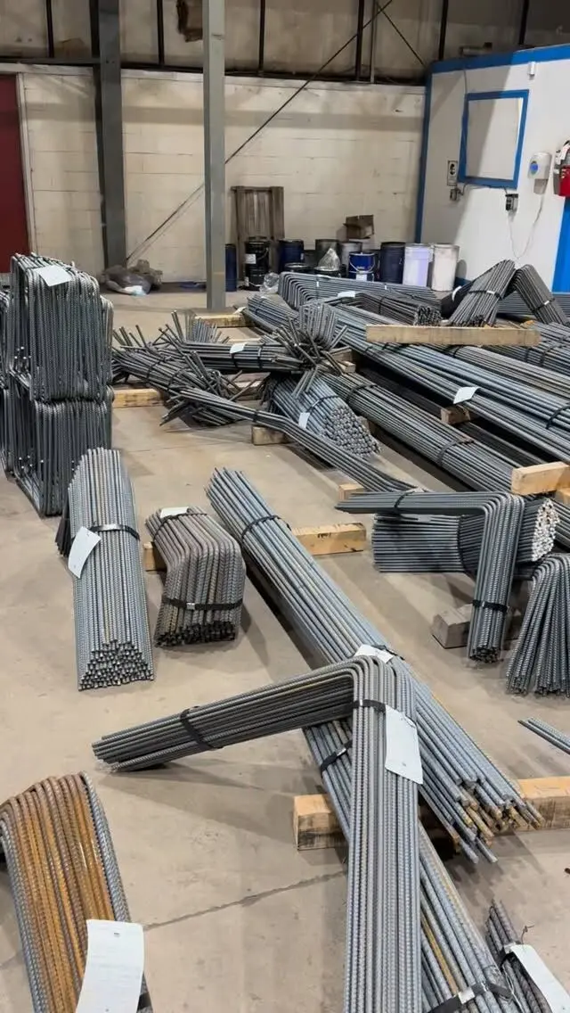
Procut provides reinforcing steel estimates and detailing from your structural drawings, then cuts, bends, tags and bundles bars from 10M to 55M so your crew places without sorting, with delivery across the GTA and Ontario.
Send your slab drawings for a free take-off and quote, or see our services and rebar products.
Frequently asked questions
What does T&B mean on a slab drawing?
T&B means top and bottom: the slab has a mat of bars near the top face and another near the bottom face. Each mat usually gets its own size and spacing callout.
What do BLL and TUL mean on slab drawings?
They name the layer a bar sits in. BLL is bottom lower layer, BUL bottom upper layer, TUL top upper layer and TLL top lower layer. In a two-way mat, the bars in the outer layers sit closest to the slab faces.
How is rebar spacing shown on a slab drawing?
As size at spacing, centre to centre, such as 15M @ 300. Bars parallel to a supporting wall or beam usually start half a spacing from the support under RSIC practice, then continue at the full spacing.
Where is rebar placed in a slab on grade?
Usually in the upper part of the slab for crack control. The RSIC manual notes slab-on-grade reinforcement is generally about 50 mm below the top surface, but the drawing note governs.
What are trim bars around a slab opening?
They are extra bars placed along the sides of an opening to replace bars the opening interrupts. The designer shows their size, number and length on the drawings.