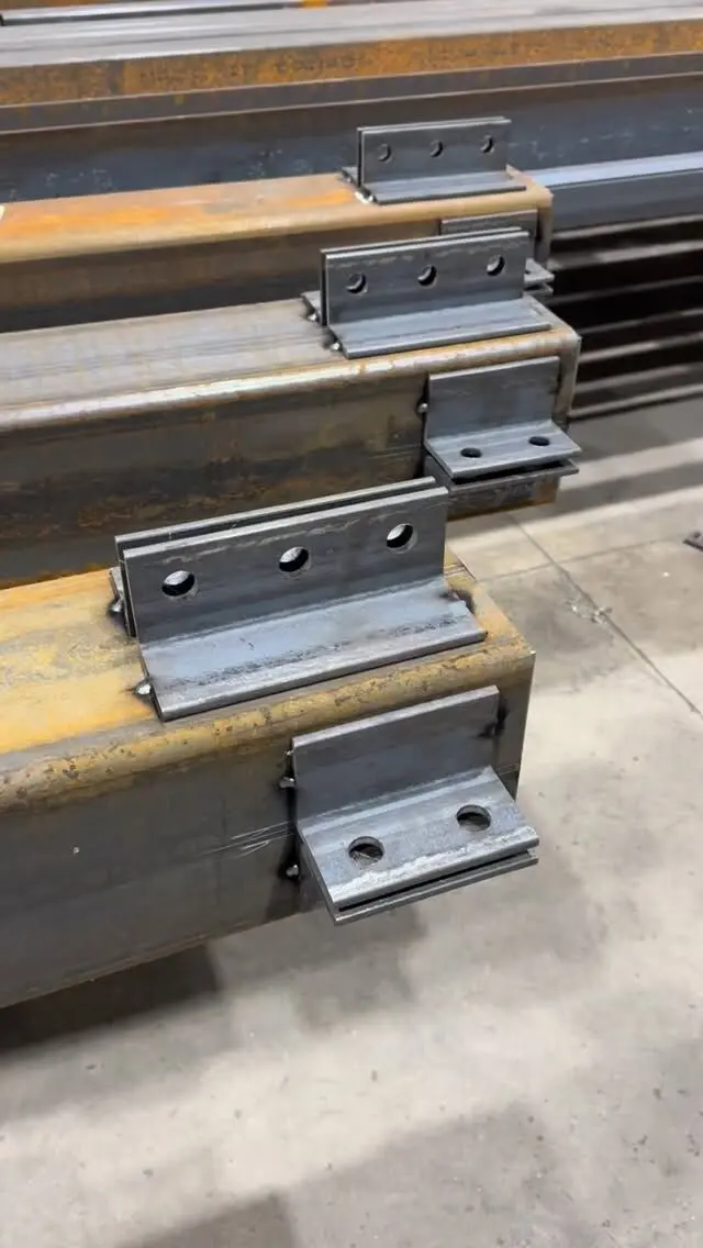
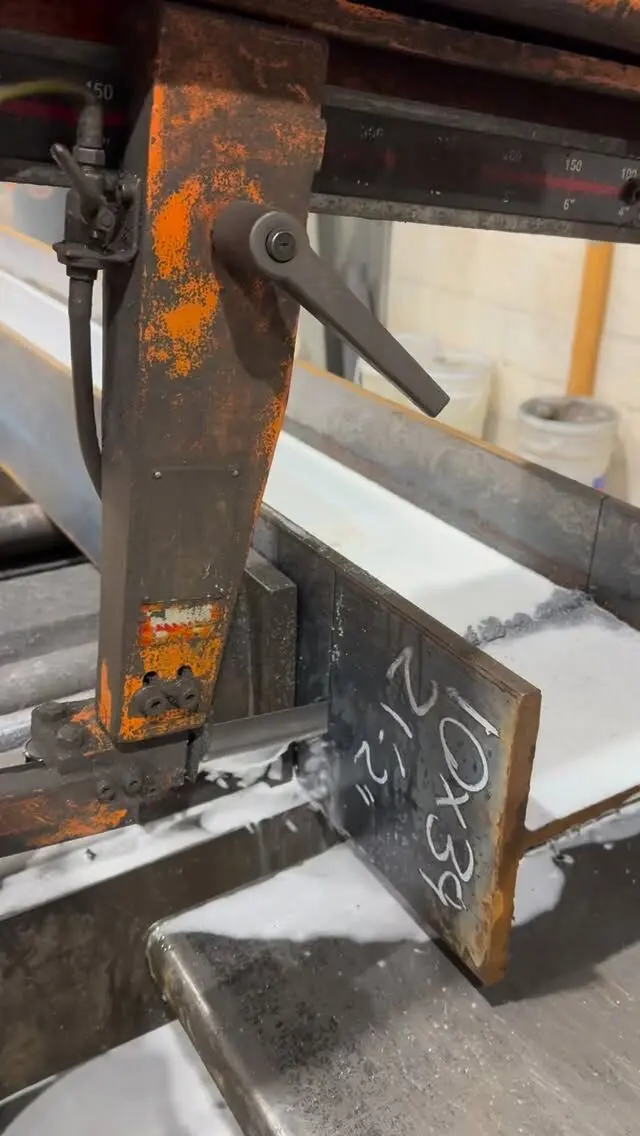
To read structural steel drawings, start with the general notes, then find each member on the framing plan by its grid lines, read its size and top of steel elevation, and follow the section and detail references to see how it connects. The engineer's design drawings tell you what is required. The fabricator's shop drawings then show exactly how each piece is built, down to every hole, plate and weld. Once you know which sheet answers which question, a steel set reads in a logical order.
This guide walks through both kinds of drawing as they appear on Canadian projects, using metric sizes. Every engineer and detailer has their own habits, so check the legend and abbreviation list on your set before relying on any of the conventions below.
Know which drawings you are holding
A steel package usually contains two families of drawings, and they answer different questions:
| Drawing | Prepared by | Answers |
|---|---|---|
| General notes | Engineer | Steel grades, bolt and weld requirements, design loads, finish, standards |
| Framing plans | Engineer | Which member goes where, its size and top of steel elevation |
| Elevations | Engineer | Bracing, columns, heights and splice locations |
| Sections and details | Engineer | Typical and specific connections, bearing conditions |
| Anchor bolt (setting) plan | Detailer | Anchor rod locations and projections for the concrete trade |
| Erection drawings | Detailer | Where each piece mark goes on site |
| Assembly (shop) drawings | Detailer | Each shipping piece with all plates, holes and welds |
If you are pricing, ordering or checking fit, you need the engineer's drawings first. If you are building or installing, you work from the reviewed shop and erection drawings. The difference between those terms is explained in shop drawings vs fabrication drawings.
Start with the general notes
The general notes sheet (often the first S-sheet in the set) carries the information that applies to every member, so read it before you look at a single beam:
- Material grades. In Canada, W-shapes and plate are commonly specified to CSA G40.21, often 350W, and HSS to G40.21 or an ASTM grade. If a member is a different grade, the notes or the plan will say so.
- Bolts. Bolt grade and diameter for typical connections, and whether joints are snug-tight, pretensioned or slip-critical.
- Welding. The welding standard and any requirement for company certification, which in Canada means a fabricator certified by the Canadian Welding Bureau.
- Connection design. Whether connections are fully shown or delegated to the fabricator's engineer, with the forces to design for.
- Finish. Shop primer, paint system or galvanizing, and any areas left unpainted (for example, faying surfaces or steel to receive fireproofing).
- Design loads and standards, usually referencing CSA S16 for steel design.
Many errors on site trace back to a note nobody read: a beam fabricated in the default grade when the plan called for something else, or primer applied where the note said bare steel.
Read the framing plans: grids, sizes and elevations
Framing plans are drawn looking down on each floor or roof. Three things make them readable.
Grid lines. Columns sit on a grid, usually letters one way and numbers the other. A beam "on grid C between 2 and 3" is unambiguous. Every dimension on the plan ties back to the grid, so start there when locating anything.
Member callouts. Each beam line carries its size, such as W310x39. That reads as a wide-flange shape about 310 mm deep weighing 39 kg per metre. If the size names are unfamiliar, our guide on how to read steel beam sizes breaks them down, including imperial equivalents. Callouts may also show:
- Camber, written as a note such as "c = 20" (mm) next to the size
- Shear studs, as a number of studs per beam or a spacing
- Reactions at the beam ends, where connection design is delegated
- Moment connections, shown with a symbol at the beam end (the legend tells you which symbol means a moment connection and which a simple shear connection)
Elevations. Plans give the top of steel (TOS or T/S) for each area, sometimes as a single note for the whole floor and sometimes beam by beam where steel steps down for a thicker slab, a depressed floor or a roof slope. A beam can have the right size and the wrong elevation, so check both.
Columns are usually listed in a column schedule rather than on the plan, giving size, base elevation, splice locations and cap or base plate references for each column line.
Follow the sections and details
Plans tell you where. Sections and details tell you how. Look for a circle or flag on the plan with a detail number and a sheet number: that is a reference to a larger drawing elsewhere in the set.
Typical details apply wherever a condition repeats: every beam to column shear connection, every beam bearing on a wall, every lintel in a masonry opening. Specific details show the unusual spots: a transfer beam, a cantilever, a connection to existing structure.
When reading a connection detail, pick out:
- What each piece attaches to (column flange, column web, another beam, concrete, masonry)
- The connection material (shear tab, clip angles, end plate, seat angle)
- Bolt number, diameter and grade, and hole type
- Weld type, size and length
- Bearing length and bearing plate size where steel sits on concrete or masonry
Our article on bolted vs welded beam connections explains why designers choose one over the other.
Weld symbols and bolt notes
Weld symbols look intimidating but follow a consistent system used across North America. The parts:
- The arrow points to the joint.
- The reference line is the horizontal line the symbol sits on. A weld symbol below the line means a weld on the arrow side of the joint; above the line means the other side; on both sides means both.
- The weld symbol itself gives the type: a triangle for a fillet weld, other shapes for groove welds and plug welds.
- Numbers to the left of the symbol give the weld size; numbers to the right give length and pitch for intermittent welds.
- A circle at the junction of arrow and reference line means weld all around.
- A flag at the same junction means a field weld, made on site rather than in the shop.
- The tail carries notes such as a process or a reference to a detail.
Field weld flags are worth looking for early. A field weld needs access, a certified welder on site and often inspection, all of which affect installation cost and schedule.
Bolt notes give quantity, diameter and grade, for example structural bolts to ASTM F3125 Grade A325. Hole notes may call for standard holes, oversized holes, or short or long slotted holes (often abbreviated SSL and LSL). Slots and oversize holes give adjustment during erection, but the engineer decides where they are allowed.
Read the shop drawings: piece marks, dimensions and views
Once the detailer has turned the design into shop drawings, each shipping piece gets its own drawing:
- Piece mark. A label such as B12 or C3. It appears on the erection drawing, in the title of the assembly drawing and on the steel itself. The erector matches mark to location.
- Main member. Size, grade and the exact cut length, with any copes, cuts or bevels.
- Views. A typical beam shows an elevation of the web plus end views and sometimes a top view of the flange. Dimension strings run from one reference end, often as running (cumulative) dimensions, so a hole location is read from the end, not from the last hole.
- Fittings. Plates, angles and stiffeners each get a part mark, listed in a bill of materials on the sheet with size, length and quantity.
- Holes and welds. Hole sizes and gauges, weld symbols for every shop weld, and field weld flags where the erector welds.
- Work points. For braces and sloped members, dimensions are given to work points where member centrelines meet, which is how the geometry is controlled.
- Finish and camber. Paint or galvanizing note, and camber where the design calls for it.
Erection drawings then show every piece mark in plan and elevation, with orientation marks so a beam is not hung backwards. Anchor bolt drawings usually come first, because the concrete trade needs them before the steel is fabricated.
Common reading mistakes
A few errors come up again and again:
- Mixing up abbreviations between trades. TOS means top of steel on a steel drawing but top of slab on many concrete and rebar drawings.
- Reading imperial sizes as metric. W8x18 and W200x27 are the same beam, not different sizes.
- Ignoring revision clouds. A revised detail on sheet S-5 can change a connection shown nowhere else.
- Treating typical details as optional. If the plan does not reference a detail but the condition matches a typical one, the typical detail applies.
- Assuming field conditions match the drawings. On renovations especially, measure before steel is fabricated.
If anything in a set is unclear, ask the engineer of record through the proper channel before fabrication, not after delivery.
Send us your steel drawings
We prepare shop drawings in-house from your structural or architectural drawings, then fabricate, mark and deliver every piece to match. If a set is incomplete or hard to read, send it anyway: we will flag what is missing as part of the take-off.
Send your drawings for a free take-off and quote, or see our shop drawing, fabrication and installation services.
Frequently asked questions
How do you read structural steel drawings?
Start with the general notes for grades, bolts, welding and finish, then use the grid lines on the framing plans to find each member. Read the member size and top of steel elevation on the plan, then go to the sections and details for connections, and finally to the shop drawings for exact lengths, holes and welds.
What does TOS mean on a steel drawing?
On structural steel drawings TOS usually means top of steel, the elevation of the top flange of a beam. On concrete and rebar drawings the same letters often mean top of slab, so always check the abbreviation list on the set you are reading.
What is the difference between structural steel drawings and shop drawings?
Structural (design) drawings are prepared by the engineer and show what is required: member sizes, elevations, loads and typical connections. Shop drawings are prepared by the fabricator's detailer and show how each piece is made, with exact lengths, holes, plates, welds and piece marks.
What is a piece mark on steel drawings?
A piece mark is a unique label for each shipping piece, such as B12 or C3. It appears on the erection drawing, on the assembly drawing for that piece and on the steel itself, so the erector can match every member to its location.