There is no single base plate size chart that works for every column, because plate size and thickness depend on the load, the anchor rod layout and the steel grade. What you can chart is how thickness responds to two numbers: the bearing pressure under the plate and how far the plate projects past the column. The tables below do exactly that, using the standard cantilever method, so you can see why a plate ends up 12.7 mm on one job and 25 mm on another.
The values are illustrations of the method for estimating and checking, not a design. The engineer of record sizes base plates on any engineered project, and for house columns the Ontario Building Code sets its own minimum.
The Ontario minimum for house columns
For steel columns in buildings designed under Part 9 of the 2024 Ontario Building Code (most houses), Article 9.17.3.2. sets the floor:
| Requirement | Value |
|---|---|
| Plate size at each end of a steel column | At least 100 mm x 100 mm |
| Plate thickness | At least 6.35 mm (1/4 in) |
| Top plate under a wood beam | Must extend across the full width of the beam |
| Top plate under a steel beam | May be omitted where the column is attached to the beam another way |
That 100 x 100 x 6.35 mm plate is a minimum, not a target. A wider beam, a heavier load or an engineered post usually calls for a bigger plate. We cover the cap and base plate rules in more detail in lally column cap and base plates explained.
Anything outside Part 9, such as commercial buildings, larger multi-unit buildings or an engineered column in a house, is designed under Part 4 of the code, with steel to CSA S16 and concrete to CSA A23.3. There, no table gives you the plate. It is calculated.
What sets the plate size
Plate plan size (the B x N dimensions on the drawings) is usually decided before thickness, and load is often not the main driver. The plate has to:
- Fit the column and its weld. The plate must be larger than the column so the fillet weld around the base has a flat surface to sit on.
- Fit the anchor rods. Rods need room for the nut and washer clear of the column and the weld, plus a minimum distance from the hole to the plate edge. Rod size, layout and edge distances are the engineer's call; see anchor bolts for base plates.
- Spread the load. The plate area has to keep the bearing pressure on the concrete or grout below what CSA A23.3 allows for that concrete strength.
- Suit the support. A plate on a narrow pier or wall has to fit the concrete with enough cover around the rods, which can limit how big it gets.
For most axially loaded columns, the anchor rod layout sets the plan size, and the concrete bearing check passes easily. That's why plate size usually comes first and thickness second.
How far the plate projects past the column
Thickness depends heavily on the cantilever length, called m: how far the plate extends beyond the critical section near the column face. A common convention puts that section at 0.95 times the outside width of a square HSS column. The table shows m for common square HSS columns on square plates.
| Column | 200 mm plate | 250 mm plate | 300 mm plate | 350 mm plate |
|---|---|---|---|---|
| HSS 102x102 | 51.6 mm | 76.6 mm | 101.6 mm | 126.6 mm |
| HSS 127x127 | 39.7 mm | 64.7 mm | 89.7 mm | 114.7 mm |
| HSS 152x152 | 27.8 mm | 52.8 mm | 77.8 mm | 102.8 mm |
| HSS 203x203 | not practical | 28.6 mm | 53.6 mm | 78.6 mm |
Calculated as m = (plate width minus 0.95 x column width) / 2.
For a W-shape column (an "I-beam" column), the plate projects different amounts past the flanges and past the flange tips, and the designer checks both directions and uses the larger cantilever. The idea is the same.
Notice what this table implies. Making the plate bigger to fit anchor rods also makes the cantilever longer, and thickness rises in direct proportion to the cantilever. A big plate on a small column can need a surprisingly thick plate even under a modest load.
Base plate thickness chart
The cantilever method treats a 1 mm strip of the projecting plate as a short cantilever loaded by the bearing pressure. Setting the factored moment equal to the plate's plastic resistance (with the CSA S16 resistance factor of 0.90) gives:
t = m x √(2 x fp / (0.90 x Fy))
where fp is the factored bearing pressure under the plate (factored axial load divided by plate area), m is the cantilever length, and Fy is the plate's yield strength. The full derivation, with a step-by-step HSS example, is in our column base plate design worked example.
Required thickness, Grade 350W plate (Fy = 350 MPa)
| Cantilever m | fp 2 MPa | fp 4 MPa | fp 6 MPa | fp 8 MPa | fp 10 MPa | fp 12 MPa |
|---|---|---|---|---|---|---|
| 25 mm | 2.8 | 4.0 | 4.9 | 5.6 | 6.3 | 6.9 |
| 40 mm | 4.5 | 6.4 | 7.8 | 9.0 | 10.1 | 11.0 |
| 50 mm | 5.6 | 8.0 | 9.8 | 11.3 | 12.6 | 13.8 |
| 65 mm | 7.3 | 10.4 | 12.7 | 14.6 | 16.4 | 17.9 |
| 75 mm | 8.5 | 12.0 | 14.6 | 16.9 | 18.9 | 20.7 |
| 100 mm | 11.3 | 15.9 | 19.5 | 22.5 | 25.2 | 27.6 |
Values are the calculated minimum thickness in mm, before rounding up to a standard plate.
Required thickness, Grade 300W plate (Fy = 300 MPa)
| Cantilever m | fp 2 MPa | fp 4 MPa | fp 6 MPa | fp 8 MPa | fp 10 MPa | fp 12 MPa |
|---|---|---|---|---|---|---|
| 25 mm | 3.0 | 4.3 | 5.3 | 6.1 | 6.8 | 7.5 |
| 40 mm | 4.9 | 6.9 | 8.4 | 9.7 | 10.9 | 11.9 |
| 50 mm | 6.1 | 8.6 | 10.5 | 12.2 | 13.6 | 14.9 |
| 65 mm | 7.9 | 11.2 | 13.7 | 15.8 | 17.7 | 19.4 |
| 75 mm | 9.1 | 12.9 | 15.8 | 18.3 | 20.4 | 22.4 |
| 100 mm | 12.2 | 17.2 | 21.1 | 24.3 | 27.2 | 29.8 |
How to read it
Say an engineer has a factored axial load of 400 kN on an HSS 127x127 post with a 250 x 250 mm plate. The bearing pressure is 400,000 N / 62,500 mm² = 6.4 MPa, and from the cantilever table m = 64.7 mm. In the 350W chart, the m = 65 mm row at about 6 MPa reads 12.7 mm, and at 6.4 MPa the exact answer is 13.0 mm. Round up to the next standard thickness and the plate is 15.9 mm (5/8 in).
Two patterns stand out in the charts:
- Thickness follows the cantilever one for one. Double m and you double t.
- Thickness follows the square root of the load. Double the bearing pressure and t rises by only about 41%.
The factored load always comes from the engineer's analysis. The chart cannot tell you the load, and using unfactored or guessed loads will give the wrong answer.
Standard plate thicknesses in mm and inches
Calculated thicknesses get rounded up to a plate that is actually made. In Canada, plate is commonly specified by metric equivalents of fractional-inch sizes:
| Imperial | Metric |
|---|---|
| 1/4 in | 6.35 mm |
| 5/16 in | 7.9 mm |
| 3/8 in | 9.5 mm |
| 1/2 in | 12.7 mm |
| 5/8 in | 15.9 mm |
| 3/4 in | 19.1 mm |
| 7/8 in | 22.2 mm |
| 1 in | 25.4 mm |
| 1-1/4 in | 31.8 mm |
| 1-1/2 in | 38.1 mm |
| 2 in | 50.8 mm |
Not every thickness is equally easy to get in every grade, so ask your fabricator early if a drawing calls for an unusual one. For the grades base plates are usually cut from, see steel plate grades in Canada.
When the chart stops applying
The cantilever method above covers the most common case: a pinned column base carrying axial compression only, with the bearing pressure spread evenly. The charts do not cover:
- Moment. A fixed base, a cantilevered post or a column in an unbraced frame has uneven bearing pressure and tension in the anchor rods. The plate bends between the rods as well as around the column.
- Uplift. Light roofs, canopies and braced frames can pull up on the column. The plate then bends against the anchor rod nuts.
- Shear. Lateral loads go into the concrete through friction, the rods or a shear lug welded under the plate.
- Small plates on big columns. When the plate barely extends past the column, other methods (such as the effective area approach) can govern.
- Grout and concrete. The bearing check must pass for the grout pad and the concrete under it. See grouting base plates.
Any of those turns a chart lookup into a design. On engineered projects, the base plate schedule on the structural drawings lists the plate size, thickness, grade, holes and welds for each column type. That schedule is what fabrication follows.
Getting base plates made
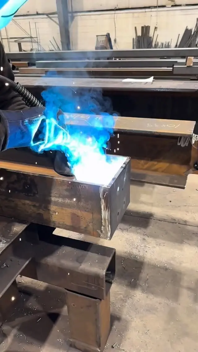
We cut, drill and weld base plates, cap plates and connection plates to your details, and supply HSS and steel posts with their plates welded on in our CWB certified shop. Send the base plate schedule or the column details from your drawings, and we'll quote the plates and posts together. If your project needs the design as well, engineering services are available; tell us about it when you ask for pricing.
Send your drawings for a quote, or browse our steel products, including plates, posts and beams.
Frequently asked questions
How thick should a base plate be?
Thick enough that the part of the plate projecting past the column does not bend under the bearing pressure from the concrete. That depends on the load, the plate size and the steel grade, so there is no single answer. For house columns built under Part 9 of the Ontario Building Code, the minimum end plate is 100 mm x 100 mm x 6.35 mm.
What is the minimum base plate thickness?
For steel columns in houses under Part 9 of the 2024 Ontario Building Code, end plates must be at least 6.35 mm (1/4 in) thick and 100 mm x 100 mm. Engineered columns have no fixed minimum in the code; the engineer sizes the plate for the actual loads.
What size base plate do I need for a steel column?
The plate has to be large enough to fit the column, the welds and the anchor rods with proper edge distances, and to keep the concrete bearing pressure within limits. In practice the anchor rod layout usually sets the plan size, and the size then sets the thickness.
Why is there no standard base plate size chart?
Because the same column can carry very different loads in different buildings. A plate that is fine under a light deck post can be far too thin under a loaded building column. The chart in this article shows how thickness changes with load and plate size, but the engineer of record sets the actual plate.