A steel plate girder is a large I-shaped beam built up from steel plates: a tall web plate welded between a top and a bottom flange plate. Instead of buying a rolled W-shape from a catalogue, the engineer chooses the depth, flange size and web thickness to suit the load and span. Plate girders are used where a rolled beam isn't deep or heavy enough, or isn't economical: bridges, transfer girders that carry columns, crane runways and long-span floors and roofs.
This guide explains how a plate girder is put together, why engineers choose one, a worked example of a built-up section's properties, and how plate girders are fabricated.
The parts of a plate girder
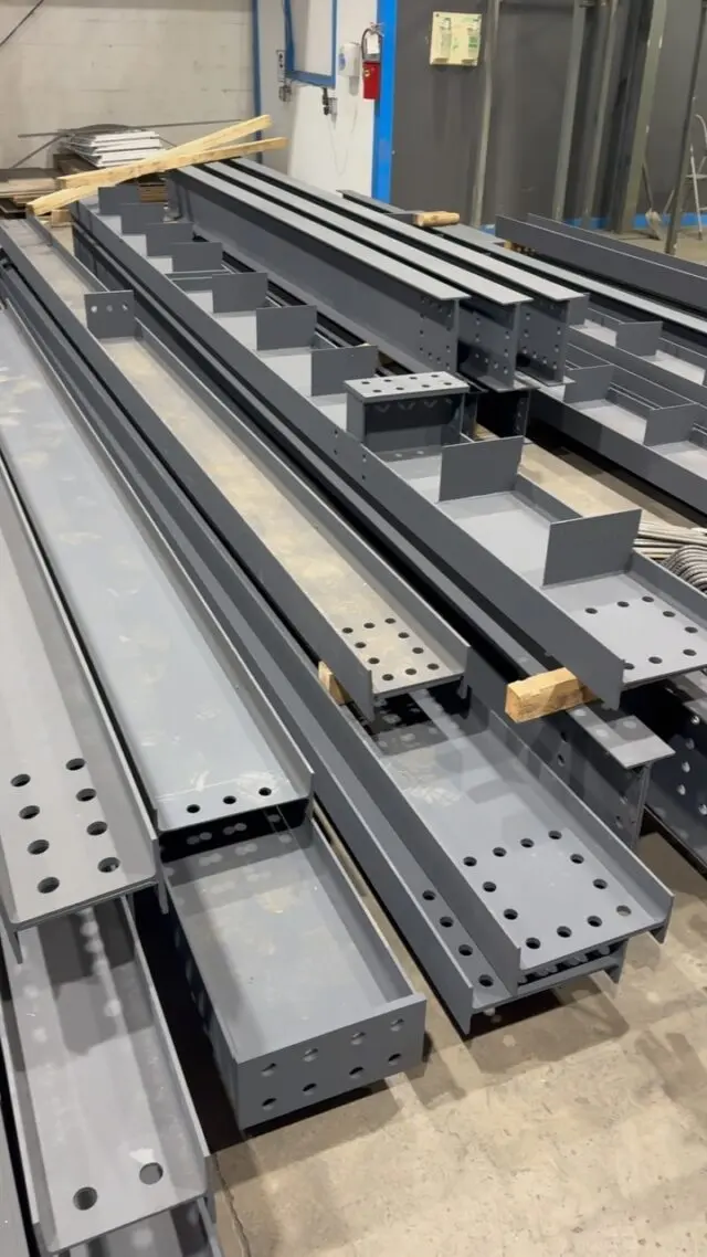
A typical welded plate girder has these parts:
- Web. The vertical plate that carries most of the shear and holds the flanges apart. Plate girder webs are deep and relatively thin.
- Flanges. Horizontal plates at the top and bottom that carry most of the bending, one in compression and one in tension.
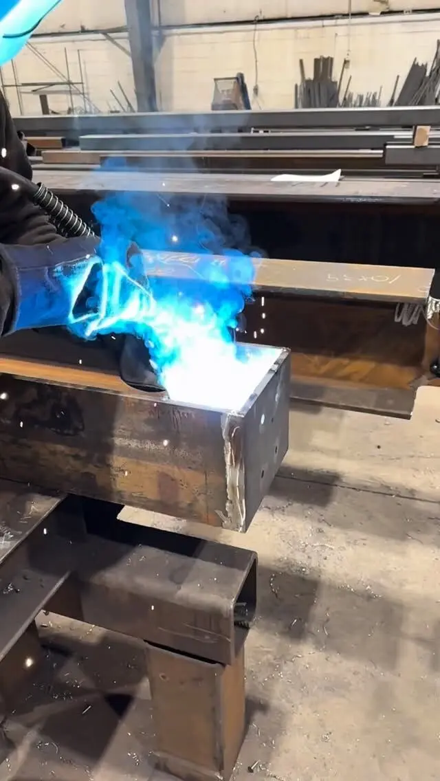
- Web-to-flange welds. Continuous fillet welds (or groove welds on heavy girders) along both sides of the web at each flange. They make the plates act as one section.
- Bearing stiffeners. Plates welded to the web at supports and under concentrated loads, to stop the web crippling or buckling where the load comes in.
- Intermediate stiffeners. Plates welded at intervals along the web, where the design needs them to increase the web's shear resistance.
- Splices and connections. Bolted or welded joints where girder sections are joined, and connection plates for beams, bracing and bearings.
Because each part is a separate plate, the designer can vary them. A flange can be thicker near mid-span where bending is highest, the web can be deeper over a support, and the top flange can differ from the bottom one.
Why use a plate girder instead of a rolled beam
Rolled W-shapes are the default for beams because they're cheap to buy and simple to fabricate. The Canadian W-shape series goes up to a nominal depth of 1100 mm, which is plenty for most buildings. Plate girders come in when:
- The span or load is beyond the rolled range. Very long spans or very heavy loads need more depth or more flange than any rolled section offers.
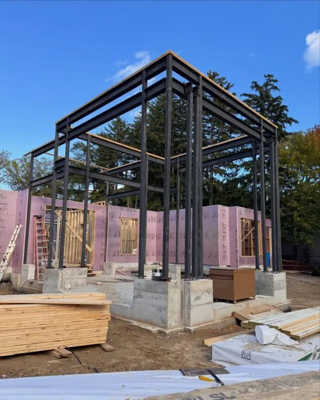
- A column has to be picked up. A transfer girder carries one or more columns from the floors above over an open space below, such as a lobby, gym or parking entrance. These loads are large and concentrated.
- The section needs to be tailored. Using exactly the steel needed, where it's needed, can save weight on long members, even though welding the girder costs more.
- Depth or shape is fixed by the design. Tapered or haunched girders, curved girders and girders that match an architectural profile are built from plate.
- Repeated or moving loads. Crane runway girders and bridge girders carry loads that move and repeat, and are designed for fatigue as well as strength.
Before choosing a plate girder for a building, engineers usually also compare a deep rolled beam, a truss and joists or a joist girder. Our post on whether a steel beam can span 30, 40 or 50 feet covers the options for long spans.
Worked example: properties of a built-up section
Here's how a plate girder's section properties are calculated. It's the same approach a designer uses to check a girder, and it shows why built-up sections are efficient. (This is a geometry illustration, not a design.)
Section: a web plate 900 mm x 10 mm, with a 300 mm x 25 mm flange top and bottom. Overall depth: 950 mm.
Area and mass:
- Web: 900 x 10 = 9,000 mm²
- Flanges: 2 x 300 x 25 = 15,000 mm²
- Total: 24,000 mm², which at 7,850 kg/m³ is about 188 kg/m
Moment of inertia (strong axis): add each plate's own I and, for the flanges, the area times the distance from the girder's centre squared.
- Web: 10 x 900³ / 12 = 607.5 x 10⁶ mm⁴
- Each flange: its centroid is 450 + 12.5 = 462.5 mm from the centre, so 7,500 x 462.5² = 1,604 x 10⁶ mm⁴, plus a negligible 0.4 x 10⁶ mm⁴ about its own axis
- Total: 607.5 + 2 x 1,604.7 ≈ 3,820 x 10⁶ mm⁴
Elastic section modulus: I divided by half the depth: 3,820 x 10⁶ / 475 ≈ 8,040 x 10³ mm³.
How does that compare with a rolled beam of about the same weight?
| Section | Depth (mm) | Mass (kg/m) | Ix (10⁶ mm⁴) | Sx (10³ mm³) |
|---|---|---|---|---|
| Built-up 900x10 web, 300x25 flanges | 950 | 188 | 3,820 | 8,040 |
| W840x193 (rolled) | 840 | 194 | 2,780 | 6,630 |
| W760x185 (rolled) | 766 | 185 | 2,230 | 5,820 |
The rolled values are from the CISC section tables. For about the same steel, the built-up section is roughly 37% stiffer than the W840x193, mostly because it's deeper and puts more of its steel in the flanges. That's the case for plate girders in one table.
What the example doesn't show is everything else the engineer has to check under CSA S16 (or CSA S6 for highway bridges): whether the flanges and web are stocky enough to avoid local buckling, the web's shear resistance and the stiffeners it needs, lateral-torsional buckling of the compression flange, bearing at supports and point loads, deflection, the web-to-flange welds and, for cranes and bridges, fatigue. Design codes allow a properly stiffened web to keep carrying shear after it starts to buckle (tension-field action), which is one reason plate girder webs can be thin. For more on how section properties feed into design, see W-beam section properties and moment of inertia.
Where plate girders are used
- Highway and rail bridges. Plate girder bridges are a common type for overpasses and medium spans, with several girders under a concrete deck. In Canada, highway bridges are designed to CSA S6, the Canadian Highway Bridge Design Code.
- Transfer girders in buildings. Carrying columns over lobbies, parking ramps, auditoriums and pools.
- Crane runway girders. Supporting overhead crane rails in industrial buildings, often with a channel or plate cap on the top flange.
- Long-span roofs and floors. Over arenas, hangars, warehouses and large open-plan spaces.
- Heavy industrial structures. Equipment platforms, conveyor supports and pipe racks with big loads.
Related built-up shapes include box girders (two webs, closed section, good in torsion and on curves) and the Canadian welded wide-flange (WWF) series of standard built-up sections, which you'll still see on drawings for older buildings.
How a plate girder is fabricated
Plate girders are a shop-intensive product. The typical sequence:
- Cutting the plates. Flanges and webs are cut from plate, and the web is often cut to a curved profile so the finished girder has its specified camber.
- Splicing plates. Long girders may need flange or web plates joined end to end with full-penetration groove welds before assembly.
- Fitting. The web is set between the flanges, squared and tacked.
- Web-to-flange welding. Long, continuous welds, often made with automatic or semi-automatic processes, with the sequence planned to control distortion.
- Stiffeners and attachments. Bearing and intermediate stiffeners, connection plates and holes are added.
- Inspection and coating. Welds are inspected to the specified level, then the girder is cleaned and coated.
All of this falls under CSA W59 for welding, and the shop has to be certified by the Canadian Welding Bureau under CSA W47.1. Our post on the CSA W59 structural welding code explains what that covers. Size matters too: a long, deep girder has to be shipped and lifted, so splice locations are often set by trucking and crane limits as much as by structure.
Built-up members and your project
If your structural drawings call for built-up girders, transfer beams or heavy welded members, send them with the rest of the steel package and we'll tell you how we'd handle them. Our shop works from in-house shop drawings with CWB certified welding, we heat camber beams where specified, and we deliver across the GTA and Ontario. Engineering services are available for projects that need them.
Send your drawings for a free take-off and quote, or see our fabrication and installation services.
Frequently asked questions
What is a steel plate girder?
A steel plate girder is a large I-shaped beam built up by welding a web plate between top and bottom flange plates, instead of being rolled in one piece at a mill. It is used where a beam has to be deeper, heavier or more tailored than the rolled W-shapes allow.
What is the difference between a plate girder and an I-beam?
A standard I-beam or W-beam is hot rolled to a fixed catalogue size. A plate girder is fabricated from plates, so the engineer can pick any depth, flange size and web thickness, change them along the length and add stiffeners. Plate girders cost more to fabricate per tonne but can use less steel for long or heavy spans.
What is a plate girder bridge?
A plate girder bridge carries its deck on two or more welded plate girders spanning between abutments and piers. They are a common type for highway overpasses and rail bridges. In Canada, highway bridges are designed to CSA S6, the Canadian Highway Bridge Design Code, not the building code.
Why do plate girders have stiffeners?
Plate girder webs are deep and relatively thin, so they can buckle under shear or under concentrated loads. Bearing stiffeners are welded in at supports and under heavy point loads, and intermediate stiffeners are added along the span where the design needs more shear resistance from the web.