CSA A23.1 defines three standard rebar hooks: a 90° hook (a 90° bend plus a straight extension of at least 12 bar diameters), a 180° hook (a semicircular bend plus at least 4 bar diameters, and never less than 60 mm), and stirrup and tie hooks of 90° or 135° with at least 6 bar diameters of extension, also not less than 60 mm. Every standard hook is bent around a minimum diameter set by the same standard, and those dimensions are what a rebar shop works to.
This post explains what each hook is for and how a hook detail is shown. For the arithmetic behind hook lengths, see rebar hook length and bend radius.
The standard hooks at a glance
| Hook | Bend | Minimum extension | Typical use |
|---|---|---|---|
| 90° hook | 90° | 12 bar diameters | Footing and wall corners, slab and beam ends, dowels |
| 180° hook | 180° (semicircle) | 4 bar diameters, at least 60 mm | Anchorage where a 90° leg will not fit |
| 90° stirrup or tie hook | 90° | 6 bar diameters, at least 60 mm | Open stirrups, ties where cover is restrained |
| 135° stirrup or tie hook | 135° | 6 bar diameters, at least 60 mm | Closed stirrups, column ties, crossties |
| 135° seismic hook | 135° | Longer, per the design | Hoops and crossties in seismic frames and walls |
Main bar hooks use the bend diameters in the rebar bending chart. Stirrup and tie hooks bend tighter, at four bar diameters for 10M and 15M.
90° hooks: the default
The 90° hook is the most common hook on a Canadian job. It is the L at the end of a footing bar, the corner bar tying two walls together and the turned-down end of a top bar in a slab edge.
It is also the default. RSIC standard practice says that when the drawings call for a hook without specifying the type, a 90° hook is assumed. That matters: if your detail needs a 180° hook to fit, it must be drawn that way.
The catch with a 90° hook is its length. A 25M 90° hook on weldable bar takes 400 mm out-to-out. In a shallow footing or thin slab edge, that leg may hit the bottom or the form, which is when designers switch to a 180° hook.
180° hooks (J-hooks)
A 180° hook turns the bar back on itself. On site it is often called a J-hook or J bend, because the bar end looks like a J. It is much more compact than a 90° hook: the overall height of the hook, called the J dimension, is only the bend diameter plus two bar thicknesses (120 mm for a 15M W-grade bar).
RSIC practice is to show the J dimension on a bar list only when the hook has to be held to a restricted size. Otherwise the shop bends the standard hook. A restricted J is made by bending around a smaller pin, and bend diameters cannot be reduced by more than 10% from the standard values without the engineer's permission.
135° hooks for stirrups and ties
Stirrups and ties need hooks that stay anchored when the outer concrete cracks or spalls. A 135° hook points back into the concrete core, so it keeps working even if the cover is lost. CSA A23.3 requires stirrup and tie hooks to have a bend of at least 135° unless the concrete surrounding the hook is restrained against spalling (by a slab, for example), in which case a 90° hook is permitted. In the 2004 edition we could check clause by clause, 90° tie hooks were also permitted in columns with concrete strength up to 50 MPa.
Crossties are single bars that tie across a column or wall. They have a 135° hook at one end and a 90° hook at the other, and the 90° hooks of successive crossties on the same longitudinal bar alternate end for end. That alternation is easy to miss on site, so check it on the placing drawings.
Seismic hooks are 135° hooks with a longer tail, used for hoops and crossties in members designed for seismic ductility. The extension is set by the design, and seismic hooks cannot be added after a stirrup is bent. Dimensions are in our guide to stirrup sizes and hook lengths.
Standard hook dimensions, 10M to 55M
For Grade 400W or 500W bar, from the RSIC Manual of Standard Practice (2020):
| Bar size | Bend diameter D | 90° hook (A or G) | 180° hook (A or G) | 180° hook J |
|---|---|---|---|---|
| 10M | 60 mm | 180 mm | 130 mm | 80 mm |
| 15M | 90 mm | 250 mm | 170 mm | 120 mm |
| 20M | 100 mm | 300 mm | 200 mm | 140 mm |
| 25M | 150 mm | 400 mm | 280 mm | 200 mm |
| 30M | 200 mm | 490 mm | 350 mm | 260 mm |
| 35M | 250 mm | 590 mm | 430 mm | 320 mm |
| 45M | 400 mm | 770 mm | 630 mm | 490 mm |
| 55M | 550 mm | 1,010 mm | 850 mm | 660 mm |
The A or G value is the allowance added to the bar's detailed length for each hook. R-grade, epoxy-coated and galvanized bar have larger bends and longer hooks; the full tables are in our hook length guide.
J bends, U bends and offset bends
Site names for bends do not always match the drawing terms. The common ones:
- J bend: a bar ending in a 180° hook.
- U bend or U-bar: a bar bent into a U with two square corners, used at wall ends, slab edges and around openings. Hairpin-shaped U stirrups are a separate stirrup shape. Each has its own type number on a bar list, explained in our guide to rebar bending shape codes.
- Offset bend (crank): two bends that jog a bar sideways while its ends stay parallel. They are used mostly for column bars where the column above is smaller, so the bars can lap inside the upper column.
Offsets have their own rules in CSA A23.3. In the edition we could check, the slope of the inclined part of an offset column bar may not exceed 1 in 6, the parts above and below the offset must be parallel to the column, and the offset bends need horizontal support from ties, spirals or the floor. Where the column face steps in by more than 75 mm, the vertical bars are not offset at all: separate dowels are lapped with the bars above. These are design details, so they must be shown on the drawings.
What a good hook detail shows
Most hook problems on site start as a missing note on a drawing. A clear hook detail gives:
- The hook angle (90°, 135° or 180°) at every hooked end, rather than relying on the 90° default.
- The direction the hook points, especially at corners, wall ends and crossties.
- Any restricted dimension, such as a J limit on a 180° hook in a thin member.
- Cover at the hook. The hook must still meet the cover requirements, which is often what decides between a 90° and a 180° hook. Our post on concrete cover for rebar has the values.
- The anchorage required. A hook's length is a fabrication dimension, while the embedment it needs is the engineer's development length.
Leg dimensions on a bar list are out-to-out, except A and G on standard 135° and 180° hooks, which are hook allowances. If a dimension must be more accurate than standard bending tolerance, it should be flagged as critical.
Hooked bars from the shop
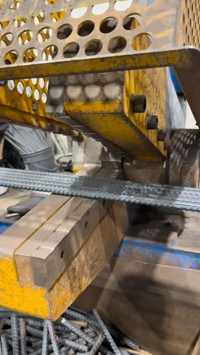
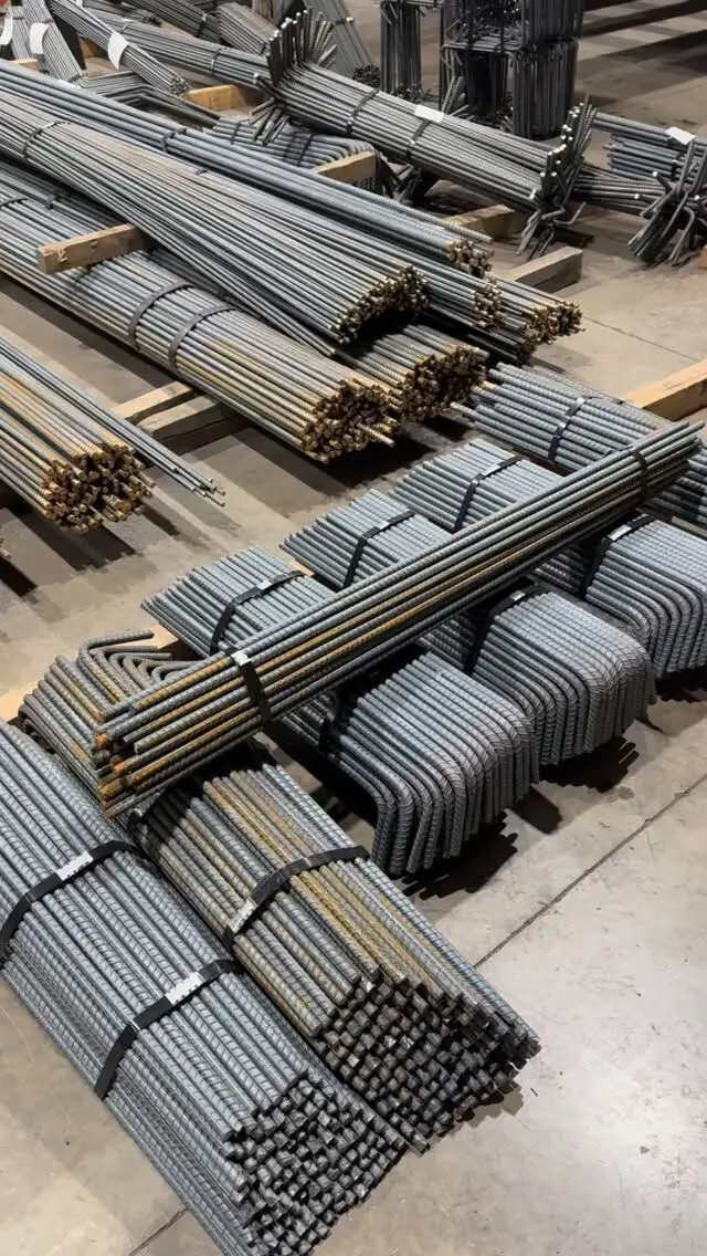
Shop-bent hooks come off the machine at the same angle, bend diameter and length every time, which is hard to match with a hand bender on site. Procut cuts and bends 10M to 55M bar to all standard shapes and hooks, tagged and bundled by mark.
Send us your drawings or bar list for a free take-off and quote, or see our rebar products for fabricated bar, dowels, stirrups and GFRP.
Frequently asked questions
What are the standard rebar hooks?
CSA A23.1 defines a 90° hook (a 90° bend plus at least 12 bar diameters of extension), a 180° hook (a semicircle plus at least 4 bar diameters, not less than 60 mm), and stirrup and tie hooks of 90° or 135° with at least 6 bar diameters, not less than 60 mm.
Which hook is used if the drawings don't say?
Under RSIC standard practice, a 90° hook is assumed when the drawings call for a hook without saying which type. If a different hook is needed, the engineer has to show it.
Why do ties use 135 degree hooks?
A 135° hook bends back into the concrete core, so it stays anchored if the cover concrete spalls. CSA A23.3 requires 135° hooks on stirrups and ties unless the concrete around the hook is restrained against spalling.
What is a rebar J bend?
On site, a J bend or J-hook usually means a bar ending in a 180° hook, which looks like the letter J. It is used where there is not enough room for the long leg of a 90° hook.
What is an offset bend in rebar?
An offset (cranked) bar has two bends that shift it sideways while keeping the ends parallel, typically in column bars where the column above is smaller. CSA A23.3 limits the slope of the inclined part to 1 in 6.