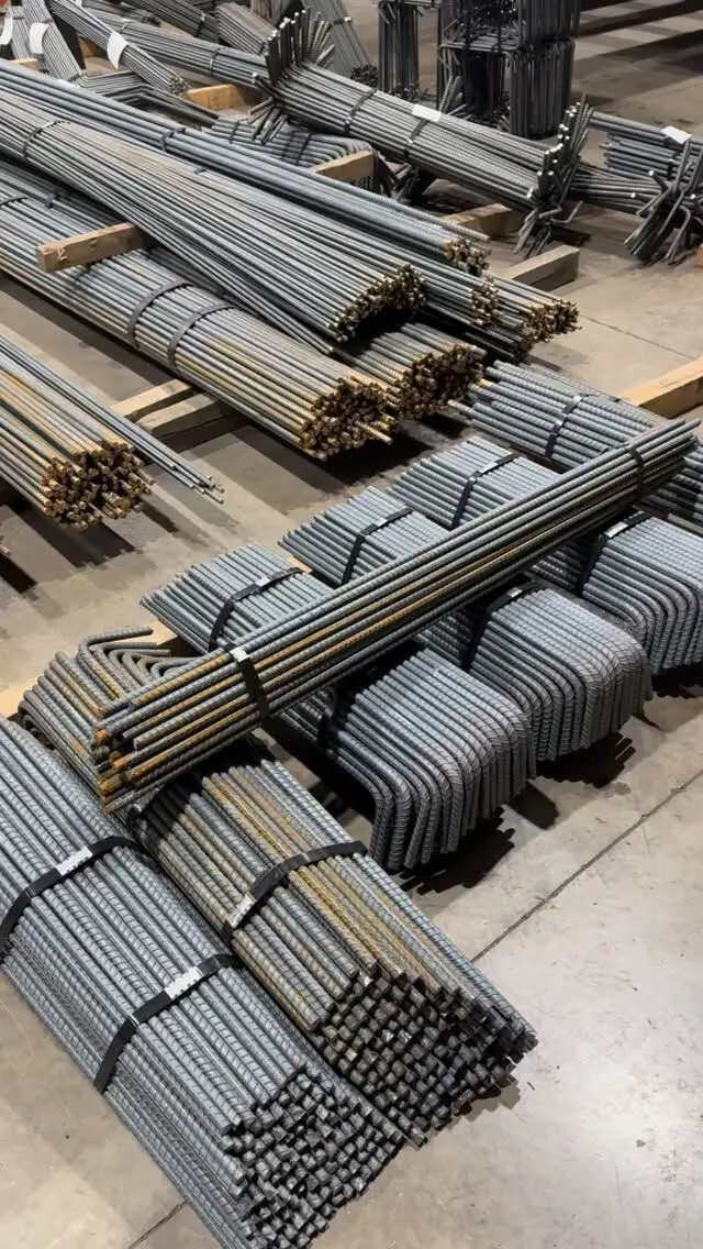
Masonry rebar shop drawings show each reinforced block wall in elevation, with every vertical bar located at a specific grouted cell, every bond beam and its bars, the dowels coming up from the footing, and the bars at openings, all keyed by mark to a bar list. They work like concrete placing drawings, with one big difference: in a concrete masonry unit (CMU) wall the steel can only go where the block has a cell, and its lengths have to suit how the mason lays and grouts the wall.
This post explains what those drawings contain and how to read them. For the design side, such as the Ontario Building Code spacing tables and grouting rules, see our guide to rebar in concrete block walls.
Who designs it, who details it, who buys it
Three parties touch block wall steel, and confusion between them causes most problems:
- The designer or engineer decides bar size, spacing, lap lengths and embedment. Under the 2024 Ontario Building Code, engineered masonry is designed to CSA S304, Design of masonry structures, and Part 9 block foundation walls use the code's own tables. The RSIC Manual of Standard Practice is blunt about this: it does not set a standard practice for masonry reinforcing, because the variety of designs is too wide, and it puts the location, size, spacing, lap length and embedment squarely on the engineer.
- The rebar detailer turns that design into placing drawings and bar lists.
- Whoever buys the steel varies. On some jobs the general contractor supplies masonry rebar; on others it is in the mason's scope. RSIC tells estimators to check this before pricing, and you should check it before ordering.
The RSIC manual also tells detailers to confirm local practice before starting a masonry job, including whether shop drawings are required at all, whether a bar list is acceptable instead, the maximum bar lengths, and where laps go and how long they are. Those are good questions for you to settle up front too.
What a masonry placing drawing shows
A typical set for a reinforced block building includes:
| Sheet or view | What it shows |
|---|---|
| Wall plan | Wall lines with wall marks, grid lines and openings |
| Wall elevations | Each wall drawn flat, showing every vertical bar, bond beam and opening |
| Sections | Bar position in the wall thickness, dowel hooks, bond beam bars, laps |
| Opening details | Jamb bars, lintel or bond beam bars over the head, sill bars |
| Footing dowel layout | Dowel locations matched to the cells the verticals will occupy |
| Bar list | Mark, quantity, size, length and bend type for every bar |
The wall elevation is the key view. Unlike a concrete wall, where a callout such as "15M @ 400 EF" covers the whole wall, a block wall elevation usually shows each vertical bar where it actually goes: at corners, wall ends, both jambs of every opening, changes in wall height, movement joints and at the typical spacing in between. That is how the Part 9 rules for reinforced block foundation walls are written too, with continuous bars at specific locations as well as a maximum spacing.
Reading the cells: spacing on the block module
Metric concrete block in Canada is laid on a 200 mm module (a 390 mm long unit plus a 10 mm joint, with courses 200 mm high). Vertical bars can only sit in cells, so on a good masonry drawing:
- Spacings are multiples of the block module, such as 400, 800, 1,200 or 1,600 mm, not arbitrary numbers. A spacing that does not land on a cell is a sign the detailer has not checked the coursing.
- Bars are dimensioned from a wall end or grid, ideally with the cell count noted, so the mason can find them.
- Bars are on the wall centre line unless the design puts them elsewhere. The Part 9 rules for reinforced block foundation walls require vertical bars on the centre line of the wall, and the section on the drawing should show it.
- Grouted cells are identified. Every cell with a bar has to be grouted solid. Some designs also call for extra grouted cells without bars; the drawing or notes should make clear which is which.
If the footing dowels were set before anyone checked the block layout, this is where it shows. A dowel that lands under a web instead of a cell either gets bent over in the field or abandoned, neither of which the engineer will like. The dowel layout should be drawn from the coursing plan; our post on footing to wall dowels covers the dowels themselves.
Bond beams, openings and corners
Horizontal steel in a block wall is concentrated in bond beams: courses of special units with the webs cut down so a horizontal bar can sit in a continuous grouted channel. On the drawings, look for:
- Bond beam locations marked on each elevation by course or elevation, typically at the top of the wall, at floor levels and at the heads and sills of larger openings. In Part 9 reinforced block foundation walls, the code requires them at the top of the wall, at structurally connected floors, and at the sill and head of openings wider than 1.20 m.
- Number and size of bars in each bond beam, for example one or two 15M.
- Corner bars. Bond beam bars must be continuous around corners and intersections. That usually means a bent L-bar lapped with the straight bars, shown as its own mark.
- Laps in bond beam bars, with lap lengths from the engineer.
- Opening steel. Jamb bars each side, the bond beam or lintel bars over the head, and any sill bars. Where a steel lintel carries the masonry instead, the drawings should say so; see steel lintels for concrete block walls.
Bed joint reinforcement (prefabricated ladder or truss wire laid in the mortar) usually appears as a note rather than as bars on the list. It is a masonry accessory, not cut and bent rebar.
Bar lengths, lifts and laps
The biggest difference between masonry and concrete bar lists is how vertical bar lengths are chosen. They depend on how the wall is built:
- Lifting the block over the bars. Some masons set full-height verticals and thread each block down over them. That is awkward with tall bars, so lengths may be limited.
- Building the wall, then dropping bars in. The wall goes up and bars are placed down the cells before grouting, often in stages that match grout lifts.
- Short bars with laps. Verticals are supplied in shorter pieces, each lapped with the one below as the wall rises and is grouted.
How tall each grout lift can be, and when cleanouts are needed at the base, are governed by CSA A371, Masonry construction for buildings, and the project specification. Your mason's plan sets the bar lengths, so tell the detailer before the bar list is finished. RSIC's own estimating practice assumes short masonry verticals (1,200 mm plus a lap) unless the drawings say otherwise, which shows how much the construction method drives the order.
Lap lengths for masonry come from the designer and the masonry design standard, not from the concrete lap tables. If the drawings are silent on laps, ask; do not let the detailer guess.
Checking the drawings before approval
When block wall placing drawings come in for review, check:
- Every reinforced wall on the structural plan has an elevation.
- Verticals appear at every corner, wall end, intersection, opening jamb, change in height and movement joint, plus the typical spacing.
- Spacings land on the block module, and dowels line up with the same cells.
- Bond beams are at every level the design requires, with corner bars shown.
- Bar lengths suit the mason's lift and grouting plan, with laps where the bars break.
- Grouted cells are clearly identified.
- The bar list matches the elevations mark by mark.
For a general approach to reviewing rebar submittals, see our rebar shop drawing review checklist.
Get block wall steel detailed and cut
We prepare bar lists and placing drawings from your structural drawings and cut and bend 10M to 55M bar, including footing dowels, verticals cut to suit your lifts, bond beam bars and corner bars, tagged by wall and delivered across the GTA and Ontario. Tell us how your mason plans to build the wall and we will detail the lengths to suit.
Send your drawings for a free take-off and quote, or see our rebar detailing and cut and bend services.
Frequently asked questions
What do masonry rebar shop drawings show?
They show each reinforced block wall in elevation, with the vertical bars located at specific grouted cells, the bond beams with their horizontal bars, dowels from the footing or slab, jamb and lintel bars at openings, and laps. A bar list gives the size, length and shape of every mark.
Who designs the reinforcement in a CMU wall?
The engineer or designer. In Ontario, engineered masonry is designed to CSA S304, and Part 9 block foundation walls follow the Ontario Building Code tables. The rebar detailer only turns that design into placing drawings and bar lists.
Do block walls always need rebar shop drawings?
Not always. Local practice varies, and on small jobs a bar list with a marked-up wall plan is often accepted instead of full placing drawings. The RSIC manual tells detailers to confirm local practice first, including whether a bar list is acceptable in lieu of drawings.
Who supplies rebar for masonry walls?
It varies by project. Sometimes the general contractor buys it, sometimes the masonry contractor. Confirm who is responsible before ordering so the steel is neither missed nor bought twice.