In a reinforced concrete cantilever retaining wall, the main stem bars run vertically near the face against the soil, the heel of the footing is reinforced along its top, and the toe along its bottom, with dowels tying the stem into the footing. The bar sizes and spacing come from an engineered design, not a code table, and the cover is 75 mm wherever concrete is cast against the earth.
This post walks through where each set of bars goes and why, so you can read a retaining wall drawing, check the steel before the pour, or put together a sensible bar list. For choosing bar sizes and for ICF and block walls, see our companion post on rebar for retaining walls and ICF walls.
When a retaining wall needs an engineered design
The Ontario Building Code treats taller retaining walls as structures in their own right. Under Article 1.3.3.5 of Division A of the 2024 OBC, a retaining wall exceeding 1,000 mm in exposed height is a designated structure when it is adjacent to:
- public property,
- access to a building, or
- private property to which the public is admitted.
Designated structures fall under Part 4 of Division B, which means a structural design, and Article 4.4.4.1 requires guards along the top where the public has access. A permit is part of that process.
Lower walls and walls in private back yards are not automatically exempt from engineering. Within Part 9, Article 9.4.4.6 requires walls supporting earth, other than foundation walls built to Section 9.15, to be designed for earth pressure, with an extra allowance where the earth is not drained or carries a surcharge. In practice almost every reinforced concrete retaining wall is designed by an engineer, because the steel depends on things a table cannot capture:
- the height of retained soil and the slope above the wall,
- surcharge from driveways, parked vehicles, buildings or stored material near the top,
- soil type, bearing capacity and groundwater,
- drainage behind the wall,
- frost depth and the depth of the footing.
The bars described below follow from that design. Treat the layout as a guide to reading drawings, not as a substitute for them.
How a cantilever wall carries load
A cantilever retaining wall is an upside-down T or L. The stem rises from a wide footing; the part of the footing under the retained soil is the heel, and the part sticking out on the exposed side is the toe.
Soil pushes horizontally on the back of the stem, so the stem bends like a cantilever fixed at the footing. That bending stretches the soil face of the stem, and the stretch is largest at the base. Concrete is weak in tension, so the main bars go where the stretching happens.
The footing works in two directions at once:
- The heel carries the weight of the soil sitting on it. The heel bends so that its top is in tension, so its main bars run near the top surface.
- The toe is pushed up by bearing pressure from the ground. It bends so that its bottom is in tension, so its main bars run near the bottom.
Get this picture in your head and most of the drawing makes sense. It also explains the most expensive mistake on retaining walls: mats placed on the wrong face.
Stem reinforcement: verticals and horizontals
Vertical bars on the soil face are the main steel. They are typically the largest and closest-spaced bars in the stem. Because the bending is largest at the base, a designer may cut off every second bar partway up the wall, or step down the bar size, where the moment drops. Those cut-off heights are on the drawings and the bar list should follow them exactly.
Horizontal bars run along the length of the wall. They control shrinkage and temperature cracking and hold the vertical bars in place. On long walls they matter a great deal, because a wall restrained by its footing cracks vertically as it shrinks.
Front face steel is often lighter, and on some walls it is just horizontal and vertical bars for crack control. Whether a front layer is needed is a design decision.
The CSA concrete design standard sets the outer limits. In CSA A23.3 (the 2004 edition is the one we checked; confirm the edition named on your project), wall bars in each layer can be spaced no farther apart than three times the wall thickness or 500 mm, whichever is less (Clause 14.1.8.4), with minimum steel ratios for vertical and horizontal reinforcement. The same edition exempts exterior basement walls and retaining walls from its rule that walls over 210 mm thick carry two layers in each direction (Clause 14.1.8.3), which is why single-layer stems with the steel near the soil face are common. Our post on concrete wall rebar spacing goes through those wall limits in more detail.
In practice the spacing on a retaining wall stem is set by the steel the bending needs, so it is usually well inside the 500 mm ceiling.
Footing reinforcement: heel, toe and key
A typical cantilever wall footing carries:
- Transverse bars across the footing width, the main footing steel. Some designs use one bent bar that runs along the top of the heel and wraps around; others use separate top bars in the heel and bottom bars under the stem and toe. The bar shape and laps are on the drawings.
- Longitudinal bars along the length of the wall, top and bottom, which tie the transverse bars together and control cracking along the footing.
- Shear key steel, where the design adds a key below the footing to resist sliding. Key bars usually extend up into the footing.
Footing bars sit on supports so they keep their bottom cover over the soil. Bricks, broken block and stones are not acceptable chairs; use proper supports with sand plates or precast concrete blocks.
Dowels between footing and stem
The stem's vertical bars have to be anchored into the footing, because the base of the stem is exactly where the bending is largest. Most walls are poured in two lifts (footing first, stem second), so the footing is cast with dowels, also called starter bars, that stick up out of the footing and lap with the stem verticals.
What the drawing should tell you:
- the dowel size and spacing, which usually match the stem verticals on the soil face,
- the hook or bend at the bottom, typically turned toward the heel and tied to the bottom mat,
- the projection above the footing, which equals the required lap length,
- where laps are staggered, if the design calls for it.
Short dowels are a common and serious defect. The lap at the base of the stem has to be long enough to develop the bar, and that length depends on bar size, concrete strength, cover and position. Our lap splice chart for metric bars and the guide to footing to wall dowels explain how those lengths are worked out.
Some designers avoid the lap at the point of highest moment by running full-height verticals from the footing up, bent at the bottom. That makes long, awkward bars to hold in place during the footing pour, which is why most site crews prefer dowels. Either way, follow the drawings.
Cover for retaining wall steel
Concrete cover for retaining walls comes from CSA A23.1 Table 17 and the exposure class the designer picks. The values that come up most:
| Location | Cover in CSA A23.1 Table 17 |
|---|---|
| Cast against and permanently exposed to earth (usually the footing bottom and any face poured against the excavation) | 75 mm |
| Walls, exposure classes F-1, F-2, S-1, S-2 (freeze-thaw or sulphates, no chlorides) | 40 mm |
| Walls, exposure classes C-XL, C-1, C-3 and the A classes (chlorides and similar) | 60 mm |
The table also requires the cover to be at least a multiple of the bar diameter and aggregate size, so large bars can need more than the millimetre value. Retaining walls along driveways and parking areas often see road salt, which can push the exposed face into a chloride class. The faces that are formed and later backfilled are a judgement call for the engineer. Our concrete cover guide has the full table.
Cover is the thing to check when the stem steel is near the soil face: too much cover moves the main bars toward the middle of the wall and reduces their lever arm, and too little leaves them exposed to water and frost on the side you can never inspect again.
Common mistakes we see on retaining wall steel
- Main bars on the wrong face. The single most damaging error. Check the drawing callout for "soil face" or "earth face" and walk the wall before the pour.
- Dowels left out or too short where the footing was poured ahead of the detailing.
- Cut-off bars run full height (wasteful) or full-height bars cut short (unsafe). Follow the bar marks.
- Footing bars on the dirt. Without supports, the bottom bars lose their cover and end up in contact with the soil.
- Weep holes and drains drilled through bars or forgotten. Drainage is part of the design load; an undrained wall sees more pressure than it was designed for.
- No corner or end bars at wall returns and steps, where the drawing usually shows extra bent bars.
Getting a retaining wall bar list made
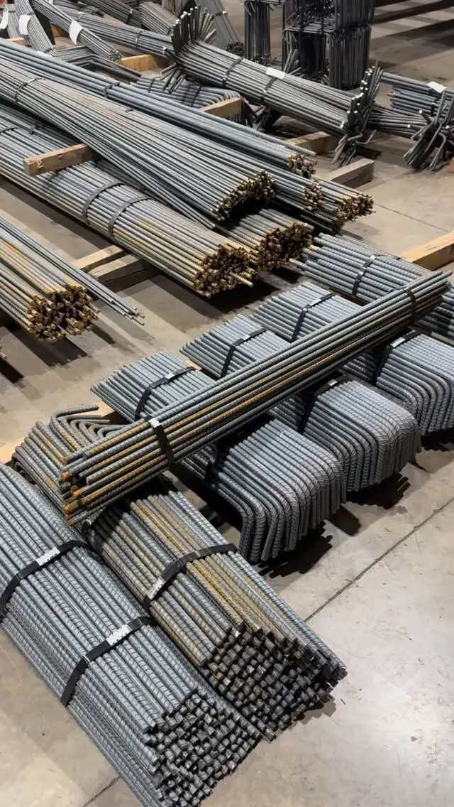
Retaining walls are a good fit for shop fabrication: the dowels, heel bars, hooked verticals and corner bars are repetitive bent shapes that are slow to make on site. We detail, cut and bend rebar from 10M to 55M, tag each bundle to the bar marks on the drawing and deliver across the GTA and Ontario. Free take-offs and quotes come from your structural drawings, and we can prepare bar lists and placing drawings from them.
Send your retaining wall drawings for a take-off and quote, or see our detailing, fabrication and installation services.
Frequently asked questions
Which side of a retaining wall does the rebar go on?
In a cantilever retaining wall the main vertical bars go near the face against the soil, because that is the side the earth pressure puts in tension. Bars placed near the exposed front face by mistake do very little, so check the face before the pour.
What is the rebar spacing for a concrete retaining wall?
It comes from the engineer's design. CSA A23.3 caps wall bar spacing at three times the wall thickness or 500 mm, whichever is less, but most retaining wall stems are spaced well inside that limit because of the bending they carry.
How much concrete cover does retaining wall rebar need?
Under CSA A23.1, concrete cast against and permanently exposed to earth needs 75 mm of cover, which usually applies to the bottom of the footing. Formed faces get a cover set by the exposure class, and the drawings state the value for each face.
Does a retaining wall footing need rebar?
A reinforced concrete cantilever wall does. The heel and toe bend under soil weight and bearing pressure, and the stem bars must be anchored into the footing through dowels or hooked bars. The engineer sets the bar sizes and spacing.
Do I need a permit for a retaining wall in Ontario?
A retaining wall over 1,000 mm of exposed height next to public property, access to a building, or private property the public is admitted to is a designated structure under the Ontario Building Code and must be designed under Part 4. Check with your municipality for lower walls too.